Medical probe with multi-fiber lumen

a multi-fiber, medical probe technology, applied in the field of medical probes, can solve the problems of missing real-time feedback during the procedure of taking a biopsy or performing surgical resection, and it is difficult to combine as a direct integral part of a single medical probe, and achieve the effect of increasing optical detection efficiency

Active Publication Date: 2014-08-21
KONINKLJIJKE PHILIPS NV
View PDF15 Cites 5 Cited by
  • Summary
  • Abstract
  • Description
  • Claims
  • Application Information

AI Technical Summary

Benefits of technology

[0005]It is an object of the invention to provide a medical probe system with increased optical detection efficiency.

Problems solved by technology

A drawback of this current way of working is that real time feedback during the procedure of taking a biopsy or performing the surgical resection is missing.
Several probes can be used to perform these measurements but in general these probes have blunt end surfaces and are therefore difficult to combine as a direct integral part of a single medical probe.
This travelling through the buffer can cause a significant amount of unwanted autofluorescence of the cladding material hampering the measurement of the tissue autofluorescence.

Method used


Image

  • Medical probe with multi-fiber lumen
  • Medical probe with multi-fiber lumen
  • Medical probe with multi-fiber lumen

Examples


second embodiment

[0041]In the second embodiment shown in FIG. 3, a multi-fiber lumen 47 which contains three optical fibers 10 is provided. Thereby, a further optical fiber is available for improving the detection efficiency.

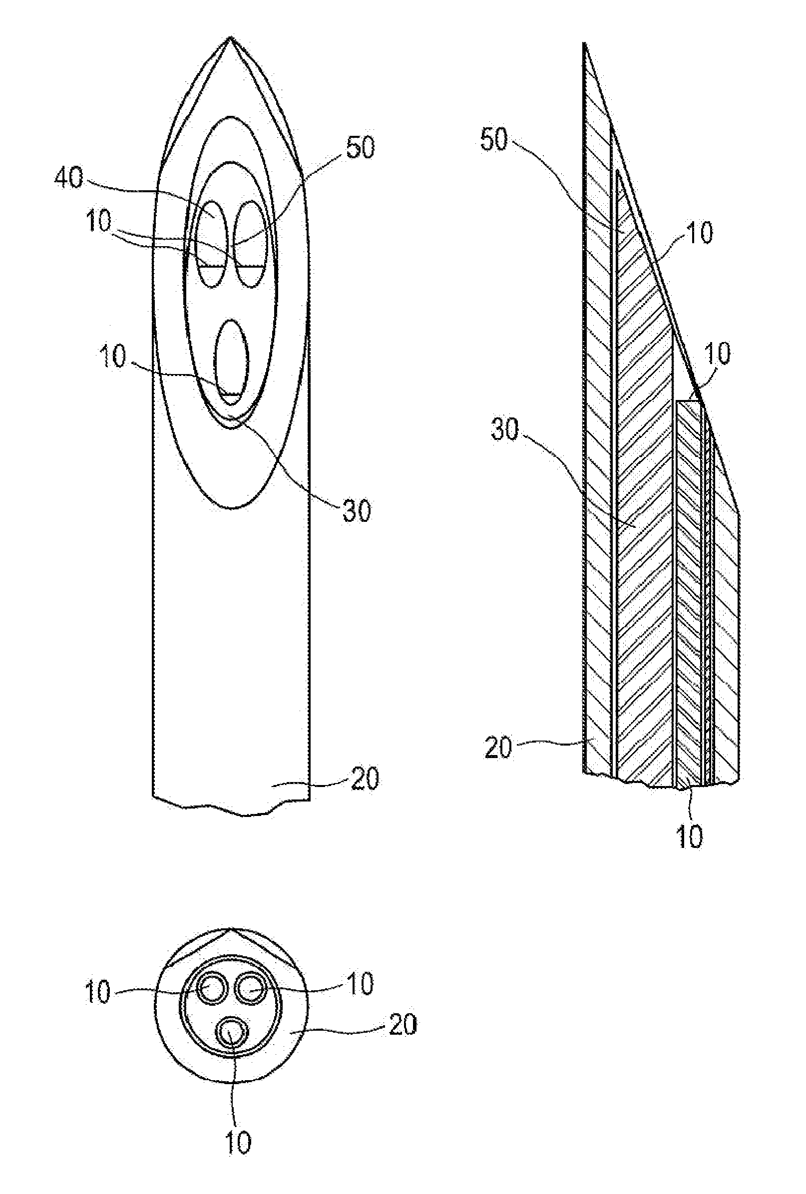
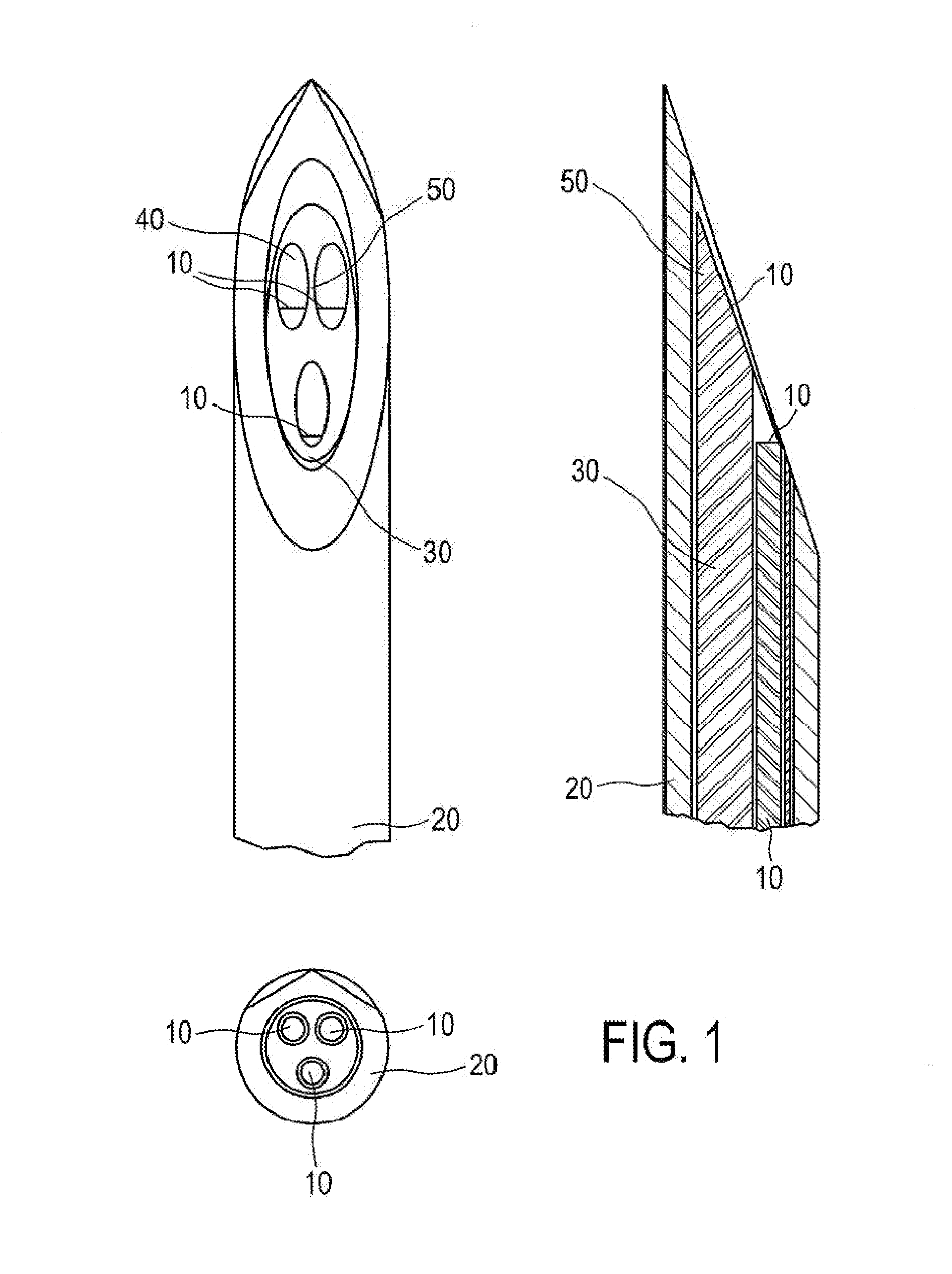
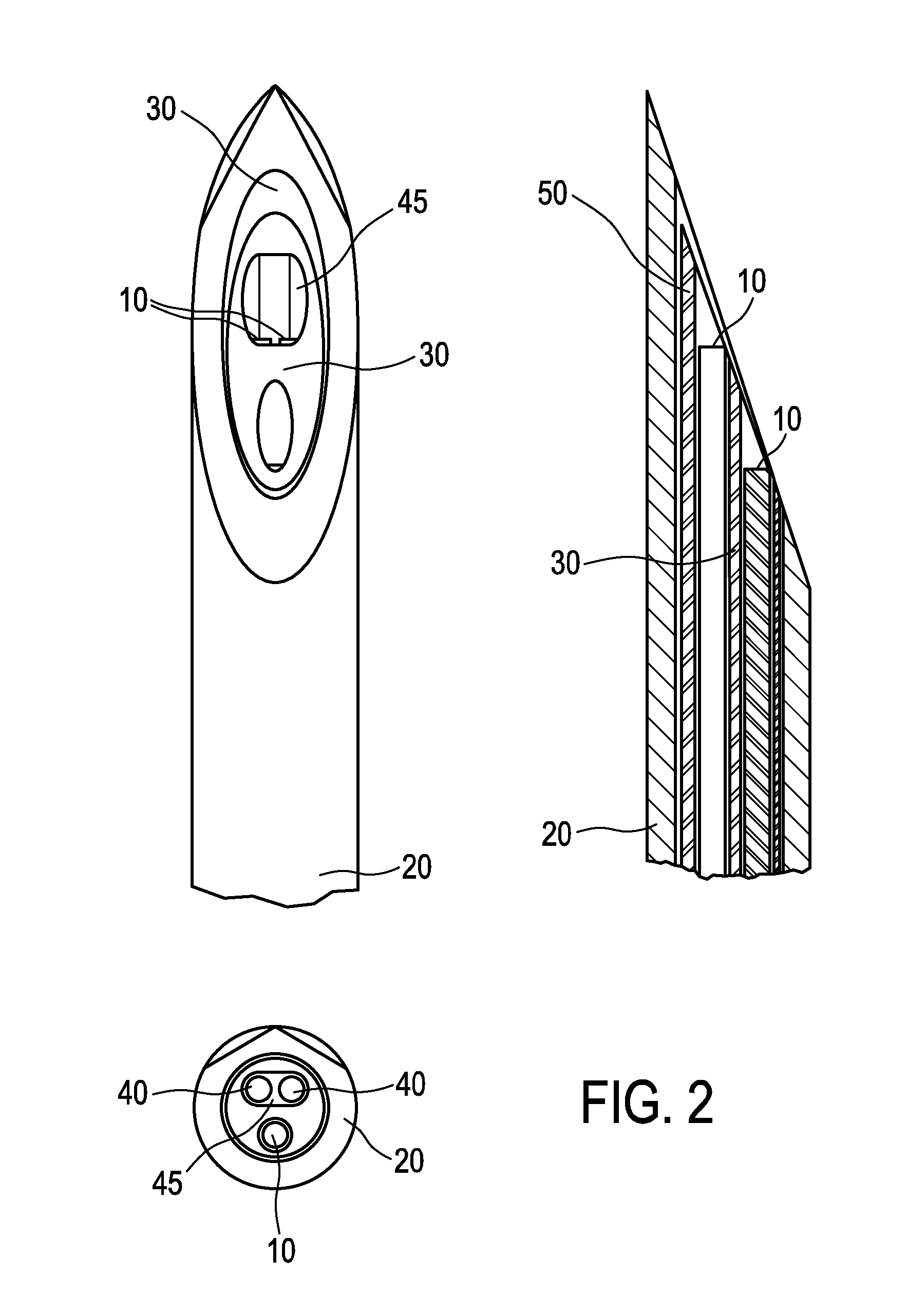
[0042]Thus, as can be gathered from FIGS. 2 and 3, the multilumen insert 30 is formed in a manner to provide a fixed distance and orientation of the contained optical fibers 10. The shape of the multi-fiber lumen 45, 47 is adapted to the number of optical fibers 10 contained therein, so that the location and orientation of the optical fibers 10 are fixed with regard to the multilumen insert 30 and thus also to any other optical fiber 10 in the multilumen insert 30.

[0043]In a third embodiment (not shown), the multi-fiber lumen 45 or 47 of the first or second embodiment may be partly or completely coated with a metal coating or a coating having low autofluorescence such that unwanted autofluorescence from needle parts (such as the multilumen tube 30) are as low as possible.

third embodiment

[0044]To manufacture the biopsy needle, the multilumen tube 30 may be made of plastic material with well defined lumen at positions that define the distance between the optical fibers 10 that can be inserted in these lumen. In the first to third embodiment, the multilumen tube 30 has at least one multi-fiber lumen 45, 47 that can contain more than one optical fiber 10. Hence there is no side wall between these two or three optical fibers 10 and no shadowing effect can occur. These two or three optical fibers 10 in the multi-fiber lumen 45, 47 are therefore well suited for fluorescence detection.

[0045]The optical fibers 10 used in the multi-fiber lumen 45, 47 are typically straight cut or only a moderate angle in such a way that (partly) total internal reflection at the fiber end is prevented. When total internal reflection occurs light reflected at the fiber end will end up in the cladding of the optical fiber 10. Depending on what material surrounds the optical fiber 10, part of th...


PUM


Abstract

The present invention relates to a medical probe which consists of a cannula with a multilumen stylet inside. The multilumen contains at least two lumen. Both the multilumen as well as the cannula may have beveled ends. In the lumen straight optical fibers (i.e.no angle end face) are present that can be connected at the proximal end to a console. The cannula, multilumen, fiber system forming the medical probe comprises at least in one of the lumen of the multilumen more than one optical fiber. Preferably the source and detector fibers for the fluorescence detection are contained in one single lumen of the multilumen.

Description

FIELD OF THE INVENTION[0001]The invention relates to a medical probe—such as biopsy needle, ablation needle or catheter—which incorporates optical fibers to perform optical measurements at the tip of the probe.BACKGROUND OF THE INVENTION[0002]In the field of oncology it is important to be able to discriminate tumor tissue from normal tissue. Typically, tissue is inspected at a pathology department after a biopsy or after surgical resection. A drawback of this current way of working is that real time feedback during the procedure of taking a biopsy or performing the surgical resection is missing. A way to provide such feedback to a medical device or medical probe, for instance a biopsy needle, is to incorporate optical fibers to perform optical measurements at the tip of the medical probe.[0003]Various optical methods can be employed with diffuse reflectance (DRS) and autofluorescence measurement as the techniques that are most commonly investigated. Several probes can be used to per...

Claims


Application Information

Patent Timeline
Patent Type & Authority Applications(United States)
IPC IPC(8): A61B1/00A61B10/02A61B18/14A61B5/00
CPCA61B1/00167A61B5/0071A61B5/0084A61B18/1477A61B10/0233A61B5/6848A61B5/0075A61B5/0086A61B2562/223
Inventor BIERHOFF, WALTHERUS CORNELIS JOZEFWINKE, AXELHENDRIKS, BERNARDUS HENDRIKUS WILHELMUSVOSS, STEPHANLUCASSEN, GERHARDUS WILHELMUS
Owner KONINKLJIJKE PHILIPS NV
Why Eureka
Try Eureka