Payment system

Active Publication Date: 2014-08-21
UNITO
View PDF11 Cites 59 Cited by
  • Summary
  • Abstract
  • Description
  • Claims
  • Application Information

AI Technical Summary

Benefits of technology

The invention is a method that ensures secure use of a payment application on a trust card at a terminal. The method involves accessing a secret for the payment application through a server system, which is secure. The trust card can only be activated with the secret for the payment application and the user's secret. Crypto-technology is used to provide the secret securely to the terminal. This ensures that even if the terminal is stolen, the user's payments cannot be made without the server system. The method allows for user authentication and enhances security. It requires minimal operator interaction, making the system simple to implement and increasing safety and dynamicity. The method also allows for context-based advertising related to the transactions.

Problems solved by technology

In known payment systems, there are several operators, and their interaction and cooperation require complex systems and a trust relationship between the actors, wherein the costs increase as multiplication of the costs for each actor.
The systems of prior art are difficult or impossible to implement without teleoperators, which further increases the complexity of the payment systems.
In some solutions of prior art, there exists a problem of the management of a payment card or a trust card with a payment functionality during the whole life cycle of the card.
The time period between the activation and the deactivation is fully incontrollable by the service provider, which increases the risk of misuse of the card.
In some solutions of prior art, lack of security in the processing of data of the trust card and other sensitive data poses a problem.
In solutions of prior art, there is a risk that an unauthorized user can access sensitive data, for example on the user's terminal.

Method used


Image

  • Payment system
  • Payment system
  • Payment system

Examples


example 1

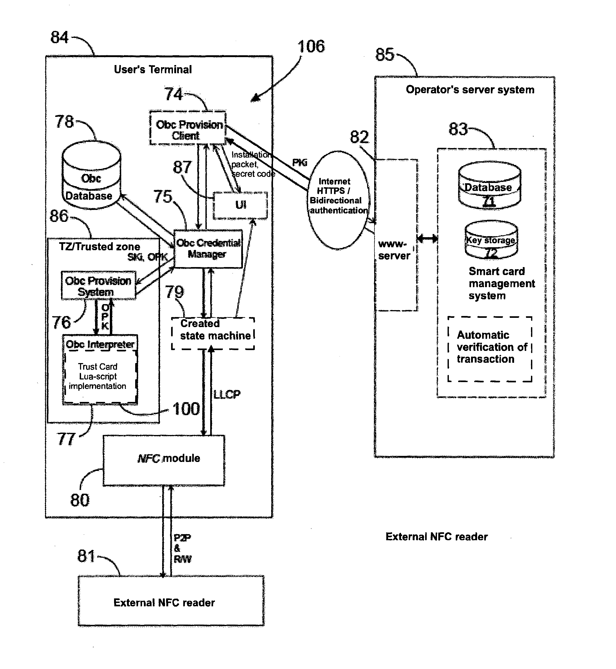
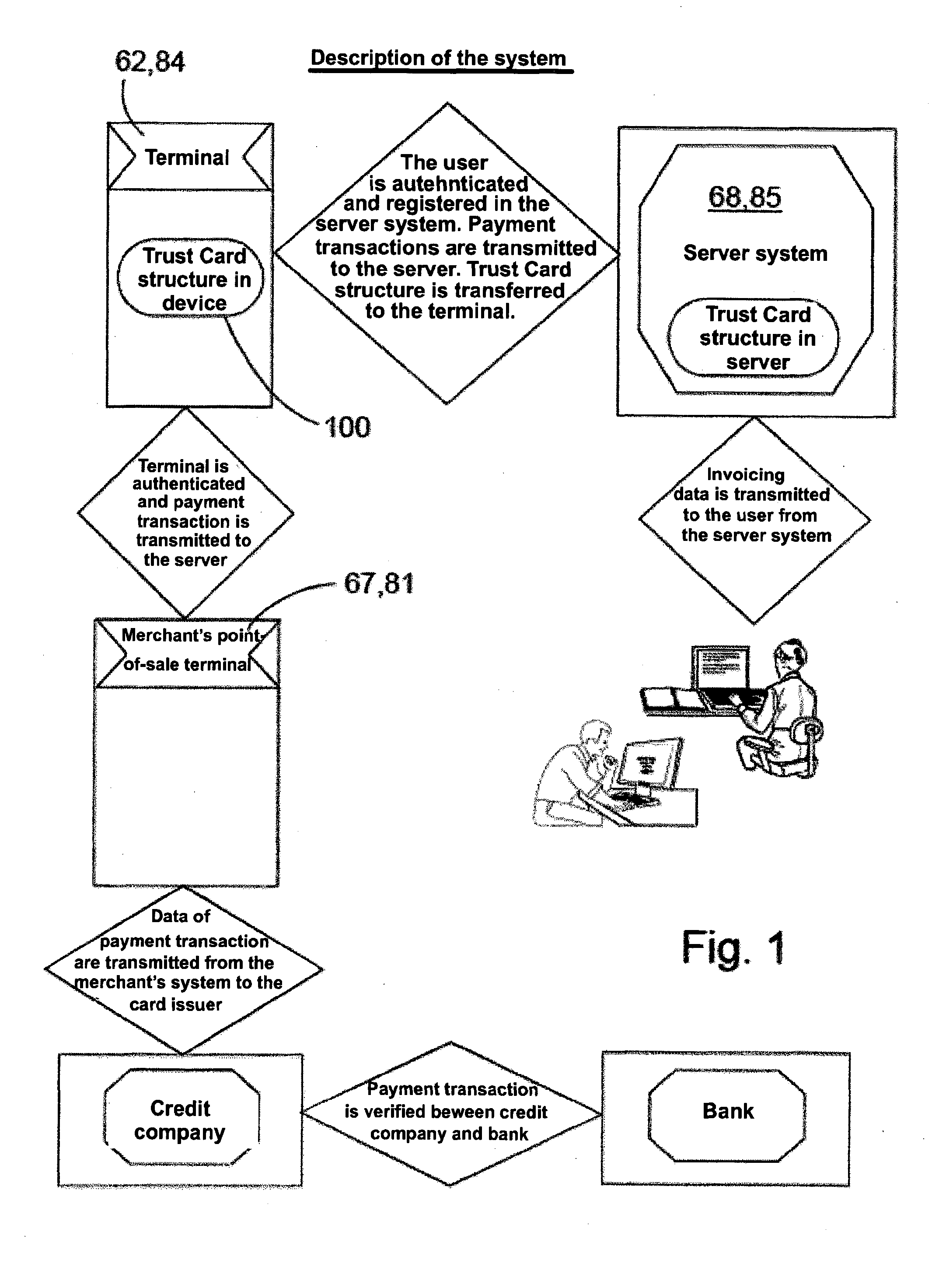
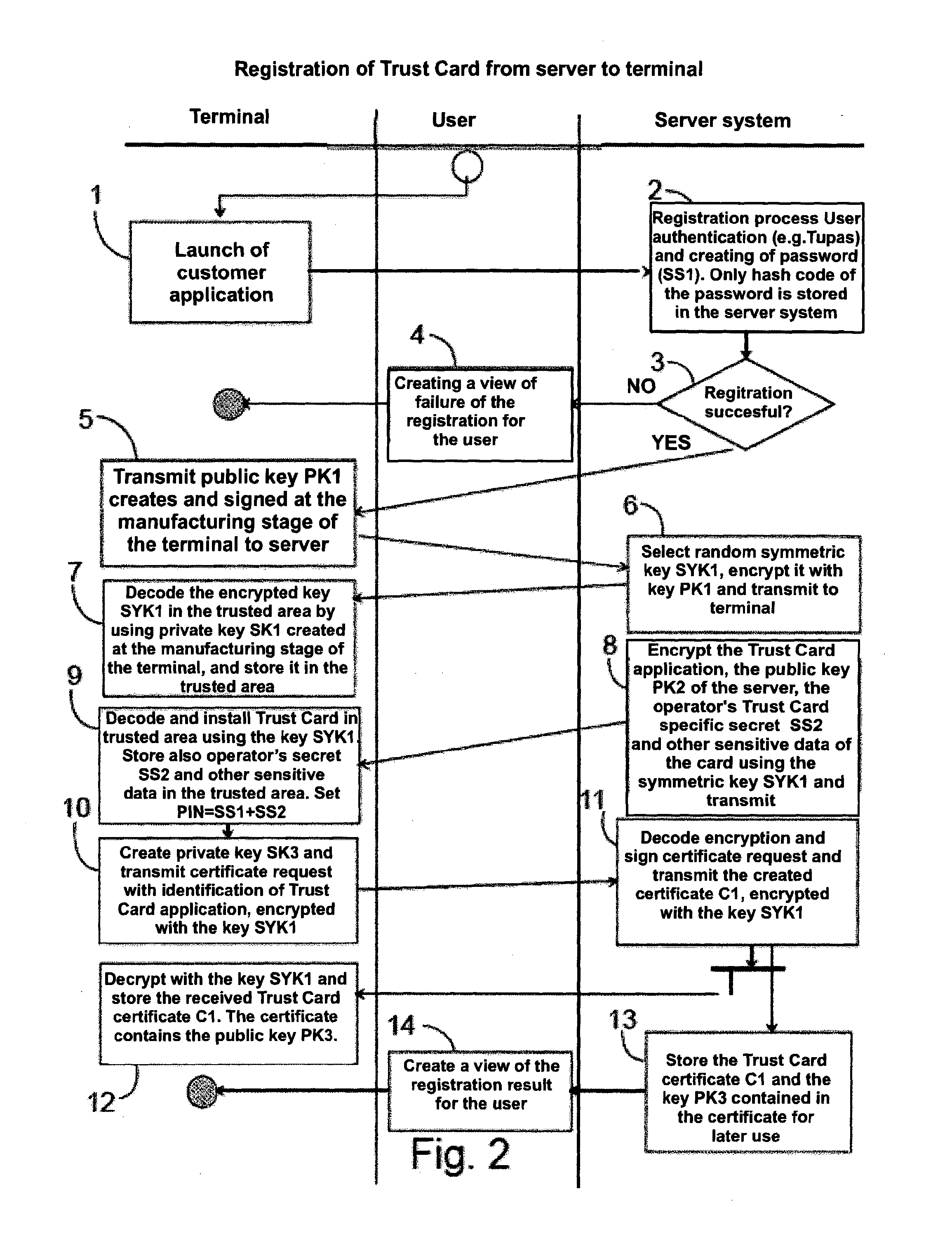
[0133]A Payment System for Producing Electronic and Secured Data to the Recipient of the Payment, the Payment System Comprising[0134]the user's terminal (62, 84) further comprising[0135]a payment application (106) for setting up payment requests,[0136]a trusted zone (64, 86) for storage and use of a programmed encryption element (100),[0137]RFID connection means (66, 80) for supplying payment data to the terminal (67, 81) of the recipient of the payment,[0138]means for communicating with the server system (63, 74) by applying a protected communications protocol, and[0139]means (65, 74) relating to said encryption element (100) for activating and deactivating the right to use the payment application (106),[0140]the operator's server system (68, 85), further comprising[0141]a management application (70, 83) for authenticating and managing a terminal,[0142]a database (71) for user specific data and keys, including the secret (SS2) of each payment application (106),[0143]means (69, 82) ...

example 2

[0147]The payment system according to Example 1, characterized in that the terminal (62, 84) comprises a credit limit counter controlled by the encryption element (100).

example 3

[0148]The payment system according to Example 2, characterized in that the RFID communication means (66, 80) of the terminal (62, 84) comprise an NFC module (80).


PUM


Abstract

A method of making a payment in which payment data is received by a user's terminal from a point-of-sale terminal, a secret of a payment application is received by the terminal from the operator's server system, a trust card is activated in the user's terminal by utilizing said secret of the payment application, and data of the trust card is transmitted from the user's terminal to the point-of-sale terminal for making the payment transaction. A trust card is created in the server system, data of the trust card is transmitted to the terminal to be used for making the payment transaction, the secret of the payment application is formed in the server system, and access to the secret of the payment application is provided to the terminal for activating the trust card for making the payment transaction.

Description

FIELD OF THE INVENTION[0001]The invention relates to methods, devices, systems, and computer programs for making payments; particularly methods, devices, systems, and computer programs in which the processing of payment data and the payment transaction take place by means of a trust card.BACKGROUND[0002]In known payment systems, there are several operators, and their interaction and cooperation require complex systems and a trust relationship between the actors, wherein the costs increase as multiplication of the costs for each actor. The systems of prior art are difficult or impossible to implement without teleoperators, which further increases the complexity of the payment systems.[0003]Systems based on the use of a SIM card are known from prior art, including, for example, the methods and systems known from FI 117586 B and FI 104937B. Here, subscriber-specific information is stored on a SIM card. These methods, too, are based on the use of teleoperators.[0004]In some solutions of...

Claims


Application Information

Patent Timeline
IPC IPC(8): G06Q20/20G06Q20/34G06Q20/40
CPCG06Q20/401G06Q20/354G06Q20/206G06Q20/20G06Q20/204G06Q20/3825G06Q20/3827G06Q20/326G06Q20/16G06Q20/3278G06Q20/382
Inventor SALMINEN, SIMOKAJAVA, TUOMO
Owner UNITO
Why Eureka
Try Eureka