System for monitoring the condition of structural elements and a method of developing such a system

a technology of structural elements and monitoring systems, applied in liquid/fluent solid measurement, instruments, machines/engines, etc., can solve problems such as clamping, derailment of railway vehicles travelling on the track, injury and loss of life,

Active Publication Date: 2014-08-28
CSIR
View PDF5 Cites 10 Cited by
  • Summary
  • Abstract
  • Description
  • Claims
  • Application Information

AI Technical Summary

Benefits of technology

[0011]It is a further object of the invention to provide a method for developing a transducer-based failure detection system, which will at least partially overcome the above disadvantages, and which will also be a novel and useful alternative to existing design methodologies.

Problems solved by technology

If a crack or break in the rail is not detected beforehand, it could result in the derailment of the railway vehicle travelling on the track.
It will be appreciated that such derailments cause financial loss and can also result in injury and loss of life.
A disadvantage associated with the above system is that the piezoelectric transducers are attached (clamped) under the crown of the rail on the outside of the track.
The piezoelectric transducers are large and cannot be attached under the crown on the inside of the track because they would interfere with the train wheels.
The removal and re-attachment (which requires re-tightening of the clamps two weeks after re-attachment) of the piezoelectric transducers increases the maintenance cost of the system and results in periods of time when the system is inoperable.
In addition, the existing system is not suited for distance in excess of 1 km, as the transmitted signal is not strong enough, and because the transducer is also not accurately matched to the particular structural element to which it will be attached from a propagation and operating frequency point of view.
The detection systems described above have generally been developed using design methodologies that do not optimally incorporate the use of mathematical modelling techniques in which the transducer and rail response is mathematically modelled, and in which the transducer is then designed in an iterative manner.
This resulted in the selection of transducers that are not necessarily optimized for a particular application, and which may result in the transducers being larger than required in practice, whilst also not performing optimally insofar as transmission and receiving of signals are concerned.

Method used


Image

  • System for monitoring the condition of structural elements and a method of developing such a system
  • System for monitoring the condition of structural elements and a method of developing such a system
  • System for monitoring the condition of structural elements and a method of developing such a system

Examples


Embodiment Construction

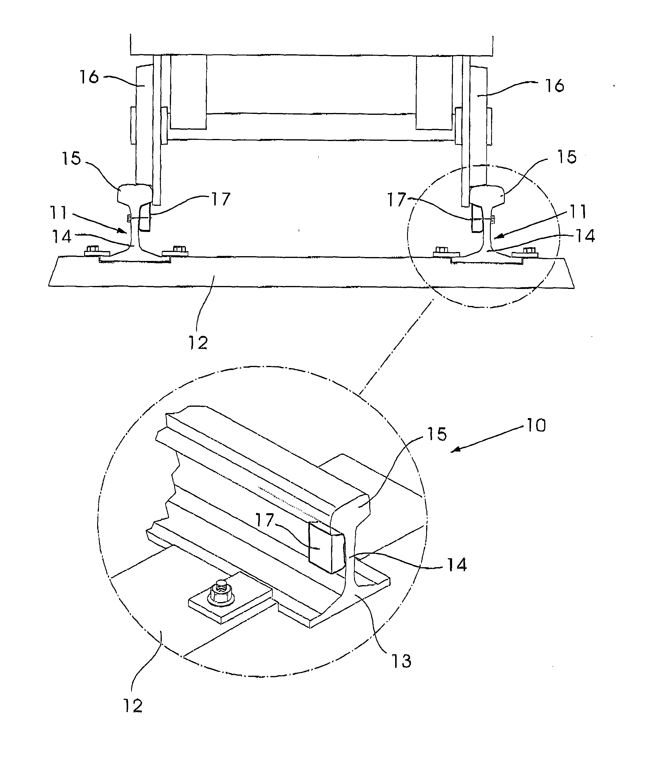
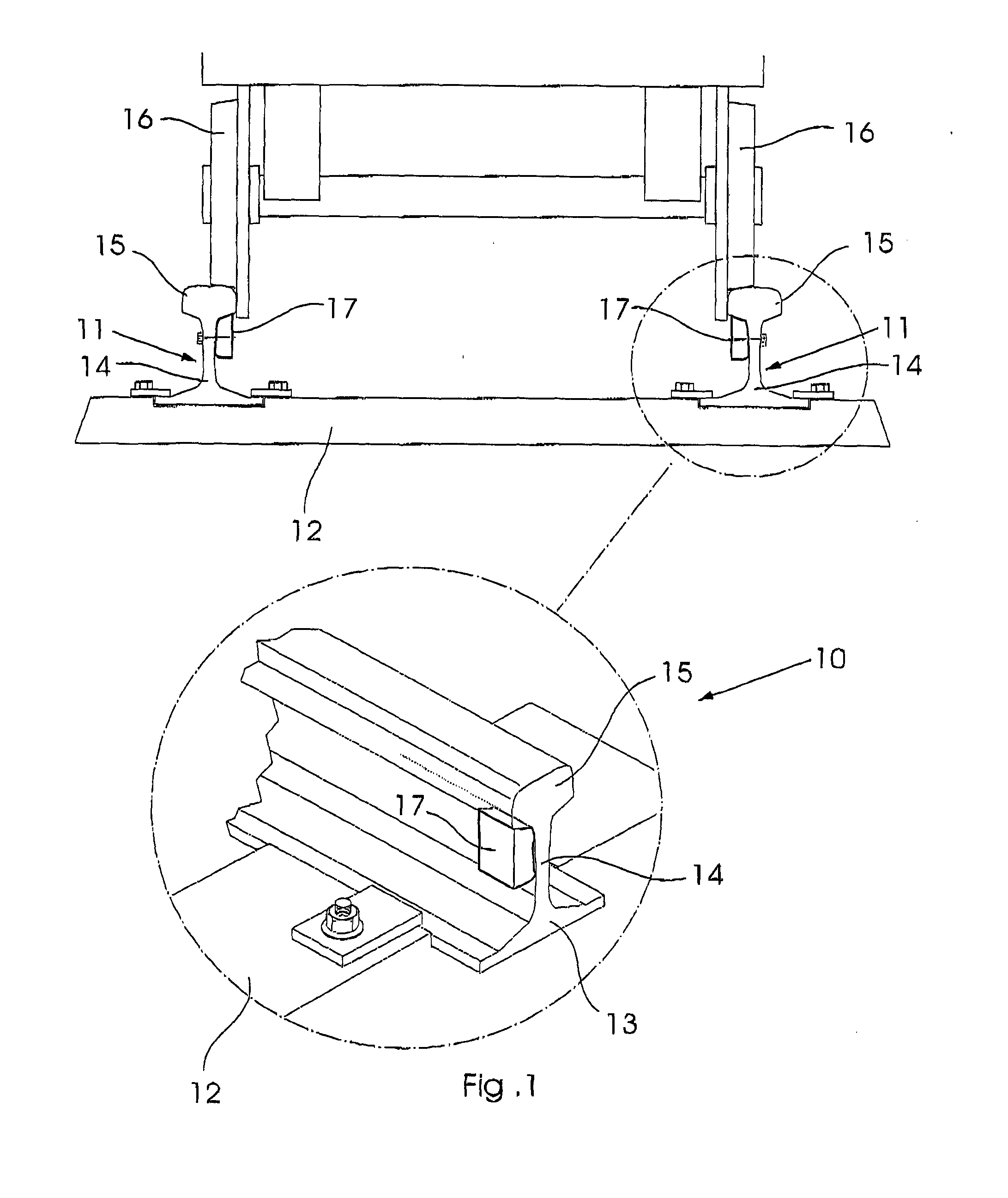
[0056]The relative small size of the transducer designed using the above design methodology enables the use of a new configuration, which is now generically described in more detail with reference to FIG. 1.

[0057]Typically, railway tracks include two parallel rails 11 that are mounted on sleepers 12. The rails 11 typically have a profile including a base 13 which rests on the sleepers 12, a web 14 extending upwardly from the base 13, and a crown 15 extending transversely from the web 14, on which the wheels 16 of a railway vehicle travel. It will however be appreciated that the system of the present invention, with modifications, can be used on any rail profile. It will be appreciated that the described embodiment relates to one particular use in a railway application, but that the system can likewise be utilised in any application involving lengths of structural steel, for example bridges and mine shafts.

[0058]In accordance with the present invention, the system 10 includes transdu...


PUM

PropertyMeasurementUnit
distanceaaaaaaaaaa
distancesaaaaaaaaaa
distancesaaaaaaaaaa

Abstract

The invention relates to a system for monitoring the condition of elongate structural elements and more particularly but not exclusively, to a system for monitoring and detecting cracks and breaks in railway rails. The invention furthermore extends to the methodology of designing and developing such a system. The method includes the steps of identifying modes of propagation and signal frequencies that can be expected to travel large distances through an elongate structural element; selecting a suitable mode of propagation and frequency of operation; designing a transducer that is adapted to excite the selected mode at the selected frequency; numerically modelling the transducer as attached to the elongate structural element; and analyzing a harmonic response of the selected mode of propagation to excitation by the transducer in order to validate the transducer design.

Description

BACKGROUND OF THE INVENTION[0001]THIS invention relates to a system for monitoring the condition of elongate structural elements and more particularly but not exclusively, to a system for monitoring and detecting cracks and breaks in railway rails. The invention furthermore extends to the methodology of designing and developing such a system.[0002]There are several methods and systems which have been proposed for monitoring the integrity of elongate structural elements, and in particular railway rails. These methods and systems are aimed at detecting cracks in the rails before they develop into complete breaks, and also to detect breaks in a railway network where they have already occurred. If a crack or break in the rail is not detected beforehand, it could result in the derailment of the railway vehicle travelling on the track. It will be appreciated that such derailments cause financial loss and can also result in injury and loss of life. Also, it should be noted that although re...

Claims


Application Information

Patent Timeline
Patent Type & Authority Applications(United States)
IPC IPC(8): G01N29/34G01N29/04
CPCG01N29/34G01N29/04G01N29/043G01N29/4472G01N2291/042G01N2291/048G01N2291/102G01N2291/106G01N2291/2623G06F17/5009G06F30/20
Inventor LOVEDAY, PHILIP, WAYNE
Owner CSIR
Why Eureka
Try Eureka