
Pneumatic tire

a technology of pneumatic tires and conductive parts, applied in the direction of tyre tread bands/patterns, vehicle components, transportation and packaging, etc., can solve the problems of difficult to improve the steering stability of any one of the dry road surfaces, the ability to always achieve the conduction performance, and the difficulty of obtaining a desired steering stability, etc., to achieve accurate conduction performance, improve the degree of freedom of design, and enhance the possibility of conductive surfaces being grounded on the road surface

Inactive Publication Date: 2014-08-28
TOYO TIRE & RUBBER CO LTD
View PDF3 Cites 6 Cited by
  • Summary
  • Abstract
  • Description
  • Claims
  • Application Information

AI Technical Summary

Benefits of technology

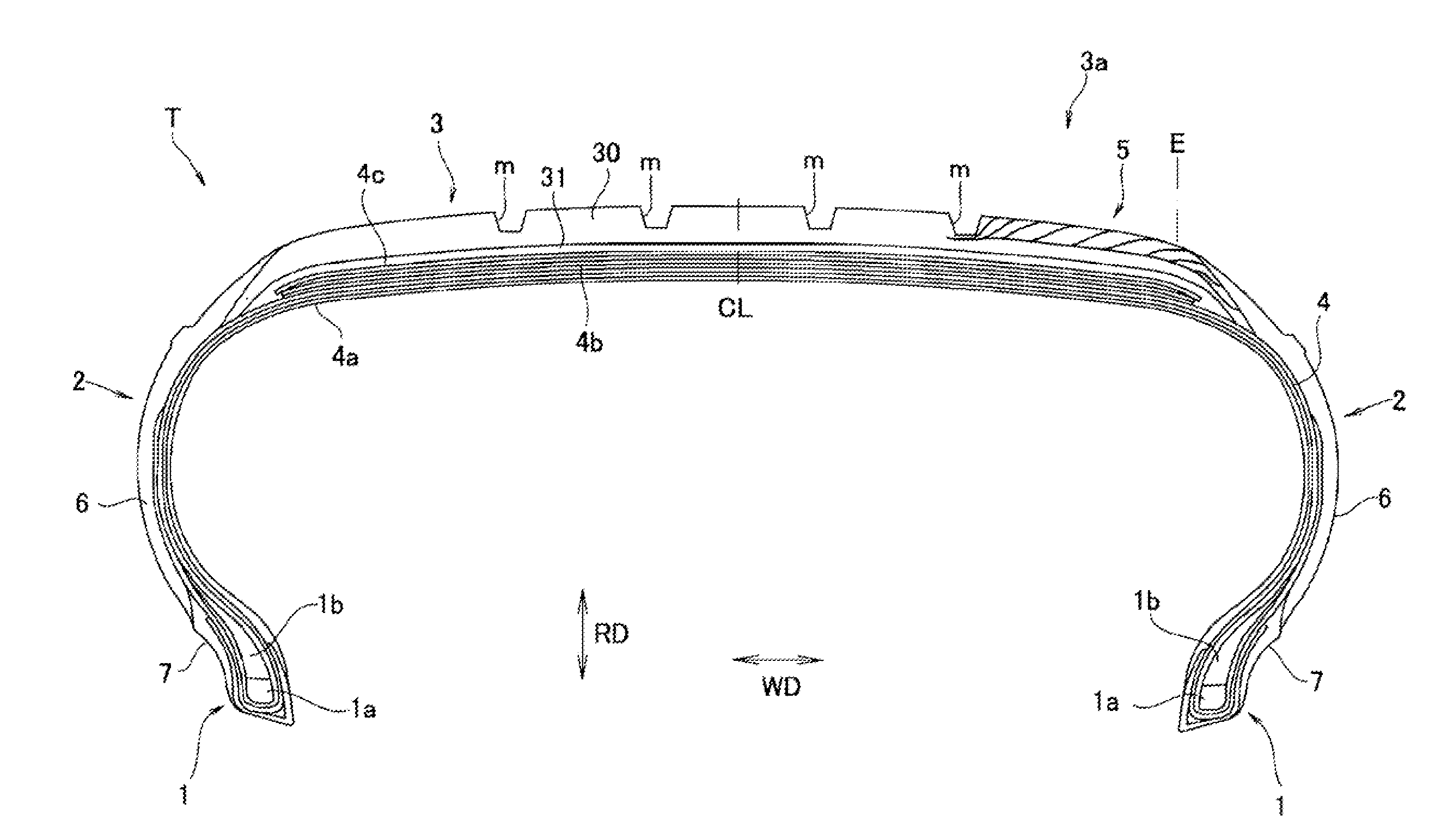
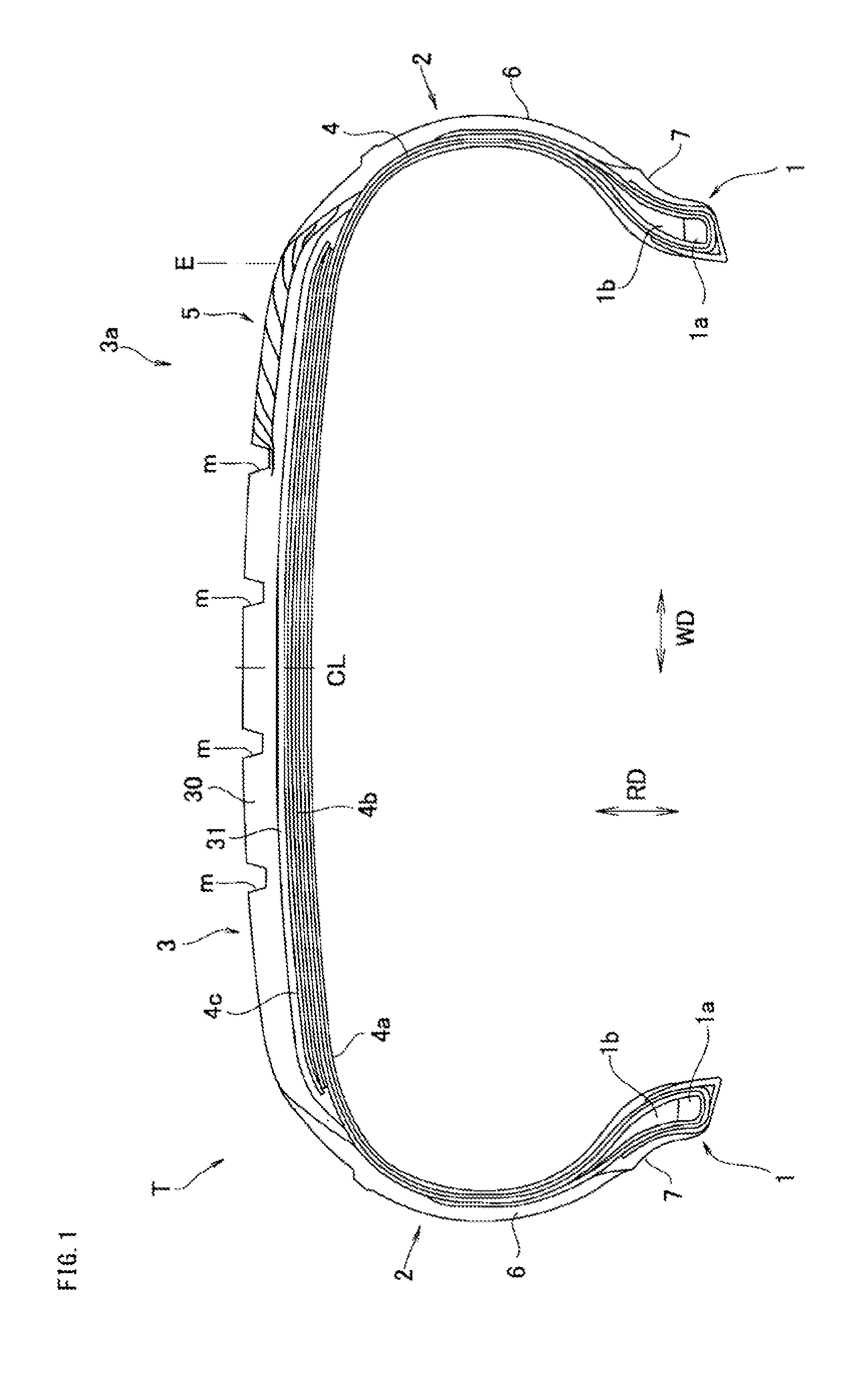
The present invention provides a tire with improved steering stability on both dry and wet road surfaces. The design includes a tread with a plurality of branch portions that enhance the likelihood of grounding and improve conduction performance. The tire has a flexible tread rigidity change portion that allows for better steering stability on both dry and wet roads. The branch portions are curved to protrude toward the outer side in the tire radial direction, which further improves the steering stability.

Problems solved by technology

However, in both the tires of JP-A-2009-126291 and JP-A-2007-290485, since the conductive portion is constructed by one line in a tire meridian circle cross section, and is exposed only at one position of a tire outer surface, there is a risk that the conductive portion comes up from the road surface on the basis of a behavior or the tire, so that it can not be said that the conduction performance can be always achieved.
As a result, the steering stability can be improved on the dry road surface or the wet road surface according to the hardness of the tread rubber, however, since these performances are in a conflicting relationship (which may be called as a fighting relationship), it is hard to obtain a desired steering stability only by setting the hardness of the tread rubber.
In other words, it is hard to improve the steering stability of any one of the dry road surface and the wet road surface in a state of maintaining the steering stability of the other, and exponentially improve the steering stability of any one of the dry road surface and the wet road surface while somewhat sacrificing the steering stability of the other.

Method used


Image

  • Pneumatic tire
  • Pneumatic tire
  • Pneumatic tire

Examples


example 1

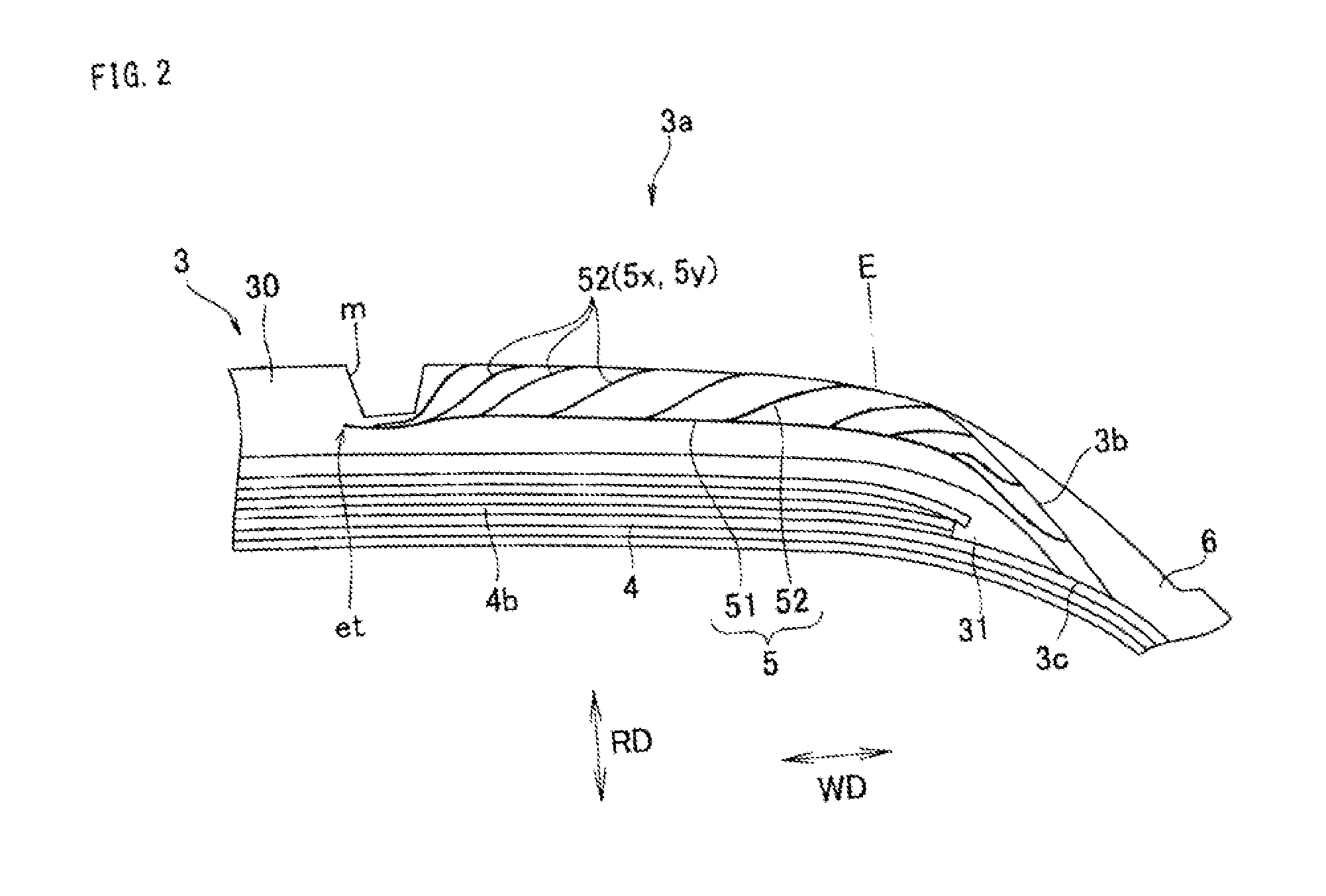
[0071]As shown in FIG. 2, the conductive portion constructed by the stem portion 51 and a plurality of branch portions 52 was formed in the tread rubber 30 of the non-conductive rubber. The angle θ of the branch portions 52 in relation to the horizontal direction was set to 70 degrees. The rubber hardness of the tread rubber 30 (the cap rubber) was set to 70 degrees, the rubber hardness of the conductive portion was set to 80 degrees, and the conductive portion 5 was made harder than the tread rubber 30.

example 2

[0072]The angle θ of the branch portions 52 was set to 50 degrees, in relation to the tire of the example 1. The other elements were set to the same as the tire of the example 1.

example 3

[0073]The angle θ of the branch portions 52 was set to 35 degrees, in relation to the tire of the example 1. The other elements were set to the same as the tire of the example 1.


PUM


Abstract

A tire has a tread rubber and a conductive portion. The conductive portion is formed so as to connect the ground surface and a side surface of a side end portion of the tread rubber in a tire meridian circle cross section. The conductive portion having a rubber hardness which is different from the tread rubber, and has a stem portion and a plurality of branch portions. The stem portion heads for an inner side in the tire width direction from the side surface of the side end portion of the tread rubber so as to terminate at an inner portion of the tread rubber. The plurality of branch portions are branched from a plurality of positions of the stem portion so as to head for an outer side in the tire width direction and be exposed to an outer surface of the tire.

Description

BACKGROUND OF THE INVENTION[0001]1. Field of the Invention[0002]The present invention relates to a pneumatic tire in which a steering stability is made appropriate as well as a conduction performance is secured.[0003]2. Description of the Related Art[0004]In recent years, for the purpose of reducing a rolling resistance of a tire which has strong relationship to a fuel consumption performance, there has been proposed a pneumatic tire in which a rubber member such as a tread rubber is formed by a non-conductive rubber blended with silica at a high rate. However, since an electric resistance is higher in the rubber member in comparison with a conventional product which is formed by a conductive rubber blended with carbon black at a high rate, and inhibits static electricity generated in a vehicle body or the tire from being discharged to a road surface, the rubber member has a problem that a problem such as a radio noise tends to be generated. Consequently, it is necessary to appropri...

Claims


Application Information

Patent Timeline
Patent Type & Authority Applications(United States)
IPC IPC(8): B60C19/08
CPCB60C19/08B60C11/0066B60C19/082
Inventor HANA, KAZUTAKA
Owner TOYO TIRE & RUBBER CO LTD
Learn More