Processing system

Inactive Publication Date: 2014-08-28
AU OPTRONICS CORP
View PDF5 Cites 2 Cited by
  • Summary
  • Abstract
  • Description
  • Claims
  • Application Information

AI Technical Summary

Benefits of technology

The present invention provides a processing stage that can hold objects using different surfaces of a polyhedron, reducing the space needed for processing. The rotary stage can also change the level height of the loading surface, making the processing more efficient and flexible.

Problems solved by technology

Because the circular platform is big, the processing system requires a large space, which is unfavorable for the plant planning and construction.
In the condition of the circular platform with an increased diameter, the displacement of the objects near the edge of the platform would be different from which near the center of the platform, thereby deteriorating the processing accuracy.

Method used


Image

  • Processing system
  • Processing system
  • Processing system

Examples


Embodiment Construction

[0023]Reference will now be made in detail to the present embodiments of the invention, examples of which are illustrated in the accompanying drawings. Wherever possible, the same reference numbers are used in the drawings and the description to refer to the same or like parts.

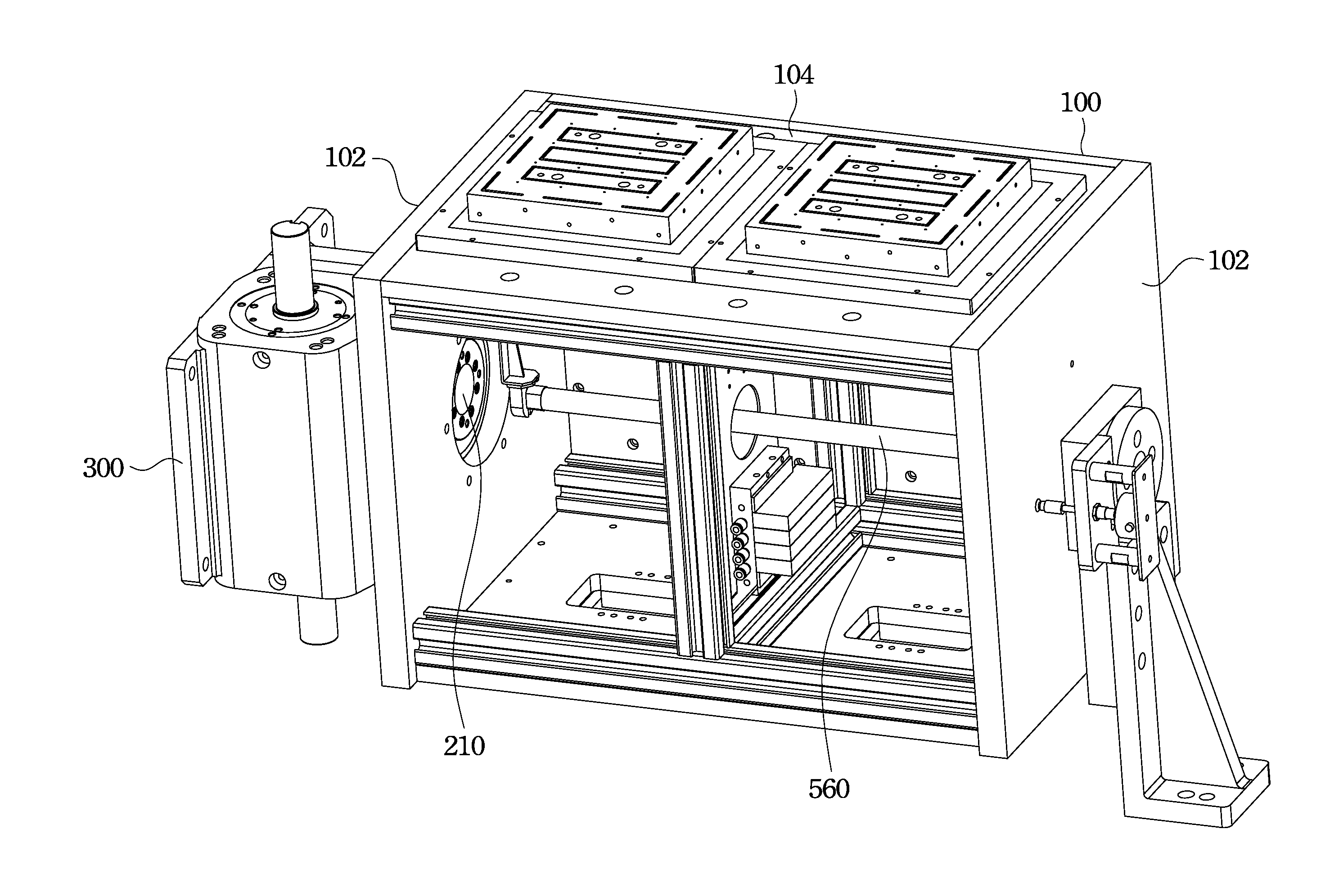
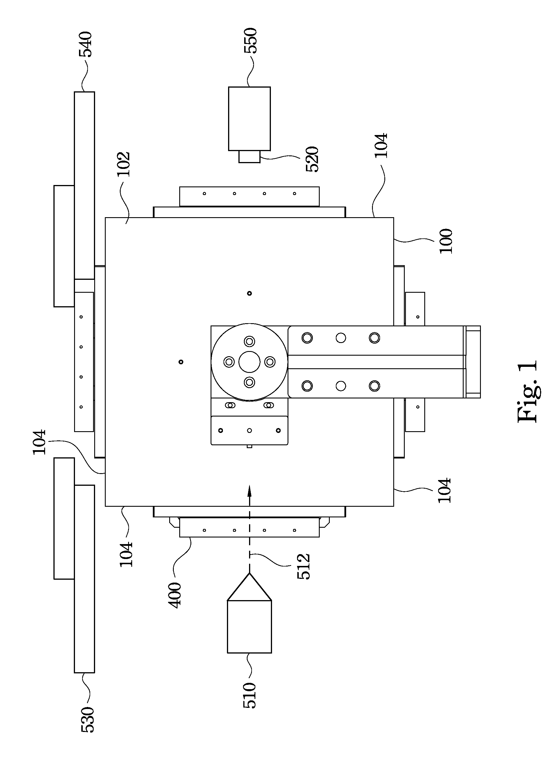
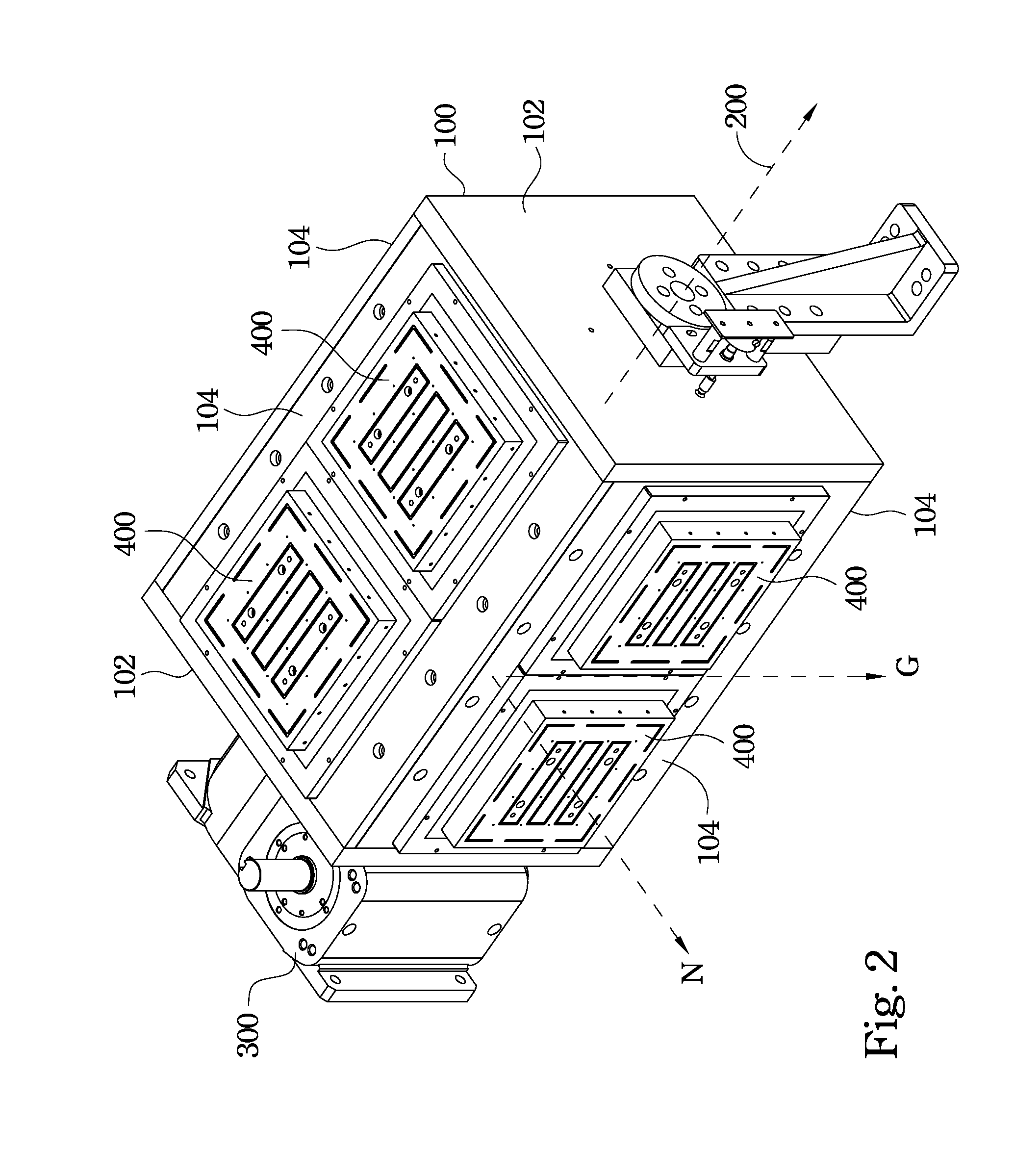
[0024]FIG. 1 is a side view of a processing system in accordance with one embodiment of the present invention. FIG. 2 is a perspective view of the rotary stage 100 of FIG. 1. As shown in FIGS. 1 and 2, the processing system includes a rotary stage 100, a rotation driver 300, a plurality of loading platforms 400 and a plurality of processing devices 510 and 520. As shown in FIG. 2, the rotary stage 100 includes two opposite end surfaces 102 and a plurality of loading surfaces 104 between the end surfaces 102. The loading platforms 400 are respectively disposed on the loading surfaces 104 of the rotary stage 100. The processing devices 510 and 520 (See FIG. 1) are respectively disposed adjacent to the loading pl...


PUM

PropertyMeasurementUnit
Angleaaaaaaaaaa
Gravityaaaaaaaaaa
Lightaaaaaaaaaa

Abstract

A processing system includes a rotary stage, at least one shaft, a rotation driver, a plurality of loading platforms, and a plurality of processing devices. The rotary stage includes two opposite end surfaces and a plurality of loading surfaces between the end surfaces. The shaft connects the end surfaces of the rotary stage. The rotation driver connects the shaft. The loading platforms are respectively disposed on the loading surfaces of the rotary stage. The processing devices are respectively disposed corresponding to the loading platforms.

Description

RELATED APPLICATIONS[0001]This application claims priority to Chinese Application Serial Number 201310058770.7, filed Feb. 25, 2013, which is herein incorporated by reference.BACKGROUND[0002]1. Technical Field[0003]Embodiments of the present invention relate to a processing system.[0004]2. Description of Related Art[0005]In a typical laser processing system, the objects to be processed are placed on a circular platform. The circular platform is rotatable, so that the objects can be moved to different workstations for processing. For example, the objects can be moved in sequence to a load / unload workstation, an alignment workstation, a laser cutting workstation and a dust cleaner workstation, and each of the workstations is equipped with a corresponding specialty machine. For example, the load / unload workstation can be provided with a loading machine and a unloading machine, and the laser cutting workstation can be provided with a laser source, so as to cut the objects and obtain des...

Claims


Application Information

Patent Timeline
IPC IPC(8): B23K26/30B23K37/04B23K26/02B23K26/38B23K26/70
CPCB23K26/422B23K26/02B23K37/04B23K37/047
Inventor TAI, YU-HUNGWEN, MENG-CHUANCHIU, YI-JUNGLEE, CHUNG-WEICHU, SHAN-LUNG
Owner AU OPTRONICS CORP
Why Eureka
Try Eureka