
Truck frame for construction machine

a construction machine and truck frame technology, applied in mechanical machines/dredgers, roofs, transportation and packaging, etc., can solve the problems of affecting the work efficiency of washing work, so as to enhance the workability of washing work and smooth operation over a long period of time

Active Publication Date: 2014-08-28
NIHON KENKI CO LTD
View PDF21 Cites 7 Cited by
  • Summary
  • Abstract
  • Description
  • Claims
  • Application Information

AI Technical Summary

Benefits of technology

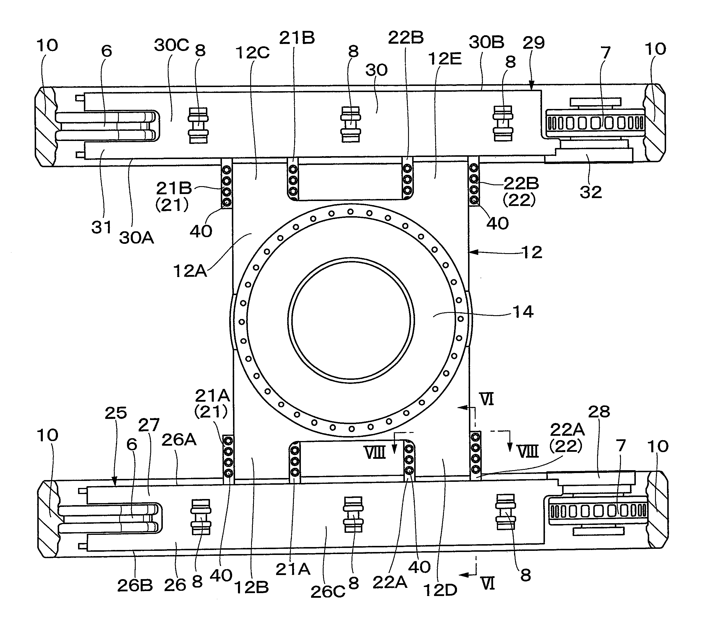
The present invention provides a truck frame for a construction machine that prevents damage to bolts for fastening side frames to front legs and rear legs of a center frame. The front and rear legs of the center frame and the front and rear leg mounting members on the inner surface plate of the side frame are mounted by the bolts inserted in the upper-lower direction. This arrangement ensures that the bolt does not come into contact with the rock while the construction machine is moving, preventing damage or bending of the bolt. The front and rear leg mounting members are only on the inner surface plates of the left and right side frames, making the center frame taller and safer to travel. The strength of each leg mounting member is enhanced, leading to a stronger mounting of the center frame and the side frames and improved reliability of the construction machine. The flange is stably placed on the mounting plate extending in the horizontal direction, ensuring strong support strength of each leg mounting member. The accumulation of earth and sand on the upper surface plate of each side frame can be restricted, improving the smooth operation of the upper roller device and enhancing workability of the washing work.

Problems solved by technology

Therefore, there are some cases when the hydraulic excavator goes through across the rock for avoidance at traveling, the rock collides with the truck frame.
In this case, since a head portion of the bolt fastening the side frame on each of the front leg and the rear leg of the center frame protrudes inside of the side frame, there is a possibility that, when the rock across which the hydraulic excavator has gone through collides with the bolt, the bolt is damaged (broken, bent or the like).
In a state where the bolt is thus bent, it requires labors and hours to perform a removal work of the side frame.
Accordingly, upon accumulation of earth and sand thereon, the earth and sand interfere with upper rollers that guide a crawler belt, possibly generating an operation failure or early abrasion of the upper roller.
Further, in a case where the accumulated earth and sand are solidified by compression or freezing, there is a problem that a large deal of labors and hours is required to scrape the earth and sand off the upper surface plate of the side frame.

Method used


Image

  • Truck frame for construction machine
  • Truck frame for construction machine
  • Truck frame for construction machine

Examples


first embodiment

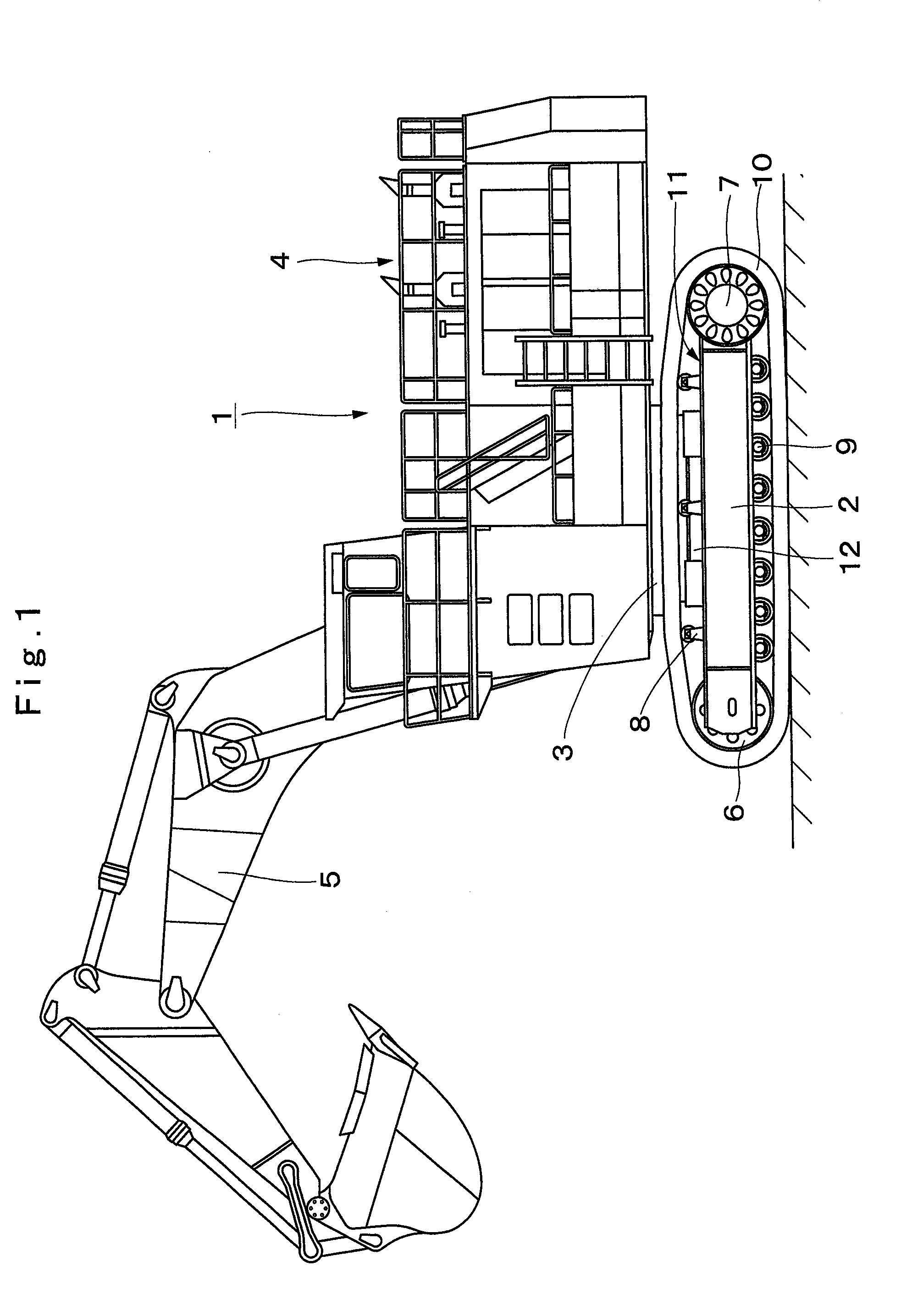
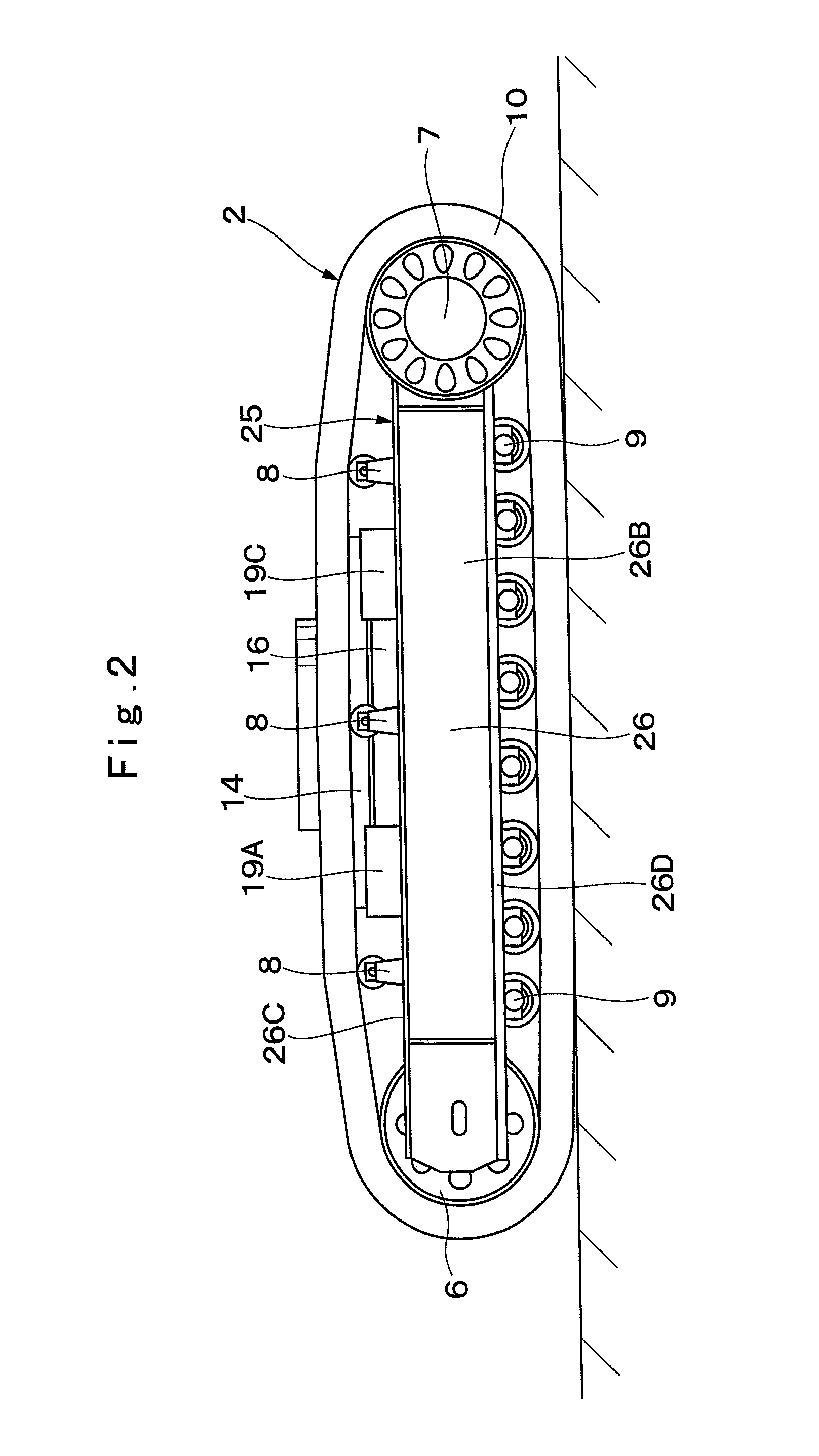
[0036]FIG. 1 to FIG. 8 show a truck frame for a construction machine according to the present invention.

[0037]In FIG. 1, designated at 1 is a hydraulic excavator as a representative example of a construction machine. The hydraulic excavator 1 is configured as an extremely large-sized hydraulic excavator. The hydraulic excavator 1 schematically comprises a crawler type lower traveling structure 2 that is capable of self-traveling, an upper revolving structure 4 that is mounted through a revolving device 3 on the lower traveling structure 2 to be capable of revolving thereon, and a working mechanism 5 that is tiltably provided in the front side of the upper revolving structure 4 thereto for performing an excavating operation of earth and sand, or the like.

[0038]The crawler type lower traveling structure 2 is provided for traveling on an irregular ground and the like where rocks roll over and a lot of concave and convex portions exist. As shown in FIG. 2 and FIG. 3, the lower traveling...

second embodiment

[0094]In the second embodiment, the two inclined covers 41 are arranged between the three upper roller devices 8 on the upper surface plate 26C of the left side frame 25, and the inclined plate 41B of each inclined cover 41 is inclined in the oblique downward side from the inner surface plate 26A toward the outer surface plate 26B of the left side frame 25. On the other hand, the two inclined covers 41 are arranged between the three upper roller devices 8 on the upper surface plate 30C of the right side frame 29, and the inclined plate 41B of each inclined cover 41 is inclined in the oblique downward side from the inner surface plate 30A toward the outer surface plate 30B of the right side frame 29.

[0095]In the hydraulic excavator 1 according to the second embodiment, the inclined covers 41 are provided in each of the upper surface plates 26C and 30C of the left and right side frames 25 and 29. Accordingly, even in a case where the earth and sand attached to the crawler belt 10 at t...


PUM


Abstract

Left and right front flanges are provided respectively in left and right front legs in a center frame. Left and right rear flanges are provided respectively in left and right rear legs in the center frame. Left and right front leg mounting members, and left and right rear leg mounting members, which protrude toward the center frame are provided respectively in left and right side frames. The respective front flanges are placed on the respective front leg mounting members, which are respectively fastened by bolts inserted therebetween in the upper-lower direction. The respective rear flanges are placed on the respective rear leg mounting members, which are respectively fastened by bolts inserted therebetween in the upper-lower direction.

Description

TECHNICAL FIELD[0001]The present invention relates to a truck frame for a construction machine that is equipped with a crawler belt, such as a hydraulic excavator, a hydraulic crane or the like, for example.BACKGROUND ART[0002]In general, a hydraulic excavator as a representative example of a construction machine comprises an automotive lower traveling structure provided with a crawler belt, an upper revolving structure that is mounted on the lower traveling structure to be able to revolve thereon, and a working mechanism that is mounted to the upper revolving structure to be able to tilt thereto. The hydraulic excavator travels on an irregular ground such as a working site or the like, and performs an excavating operation of earth and sand or the like using the working mechanism.[0003]In this case, the lower traveling structure in the hydraulic excavator is regularly configured of a truck frame that is provided with side frames at both sides of a center frame in the left-right dire...

Claims


Application Information

Patent Timeline
Patent Type & Authority Applications(United States)
IPC IPC(8): E02F9/02
CPCE02F9/02E02F3/32B62D21/186B62D55/08B62D55/088B62D55/10B62D55/084B62D21/12B62D27/06E02F9/121E02F9/08E02F9/10
Inventor TOCHIGI, KENICHI
Owner NIHON KENKI CO LTD
Learn More