
Antenna for camera

a technology for cameras and antennas, applied in the field of antennas for cameras, can solve the problems of deterioration of difficulty in ensuring a space, and affecting the lower end portion of the camera, so as to improve the efficiency of the internal layout of the camera, improve the radiation gain, and facilitate the adjustment of the resonance frequency

Inactive Publication Date: 2014-08-28
SAMSUNG ELECTRONICS CO LTD
View PDF12 Cites 14 Cited by
  • Summary
  • Abstract
  • Description
  • Claims
  • Application Information

AI Technical Summary

Benefits of technology

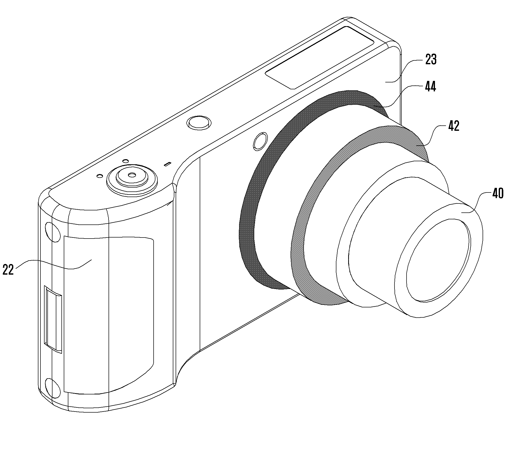
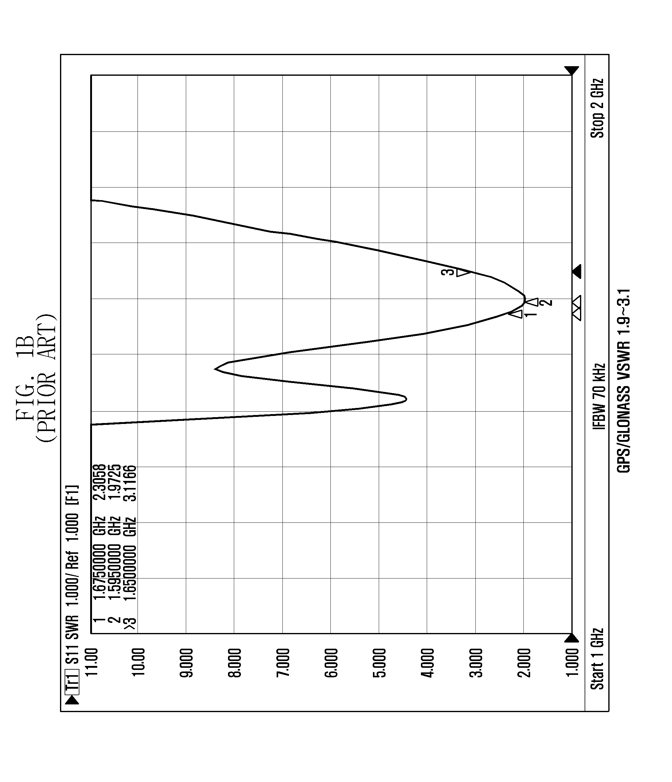
The present invention provides an antenna for a camera that makes it easy to adjust the resonance frequency of the antenna. It also increases the radiation gain through an efficient arrangement in the camera to prevent performance deterioration due to limitations caused by the surroundings of the camera or the influence of a hand effect. Furthermore, it prevents a deterioration of the radiation gain efficiency of the antenna due to the interference with a body or a lens of the camera that is made of metal. Additionally, the present invention provides a miniaturized, simple, and slim camera.

Problems solved by technology

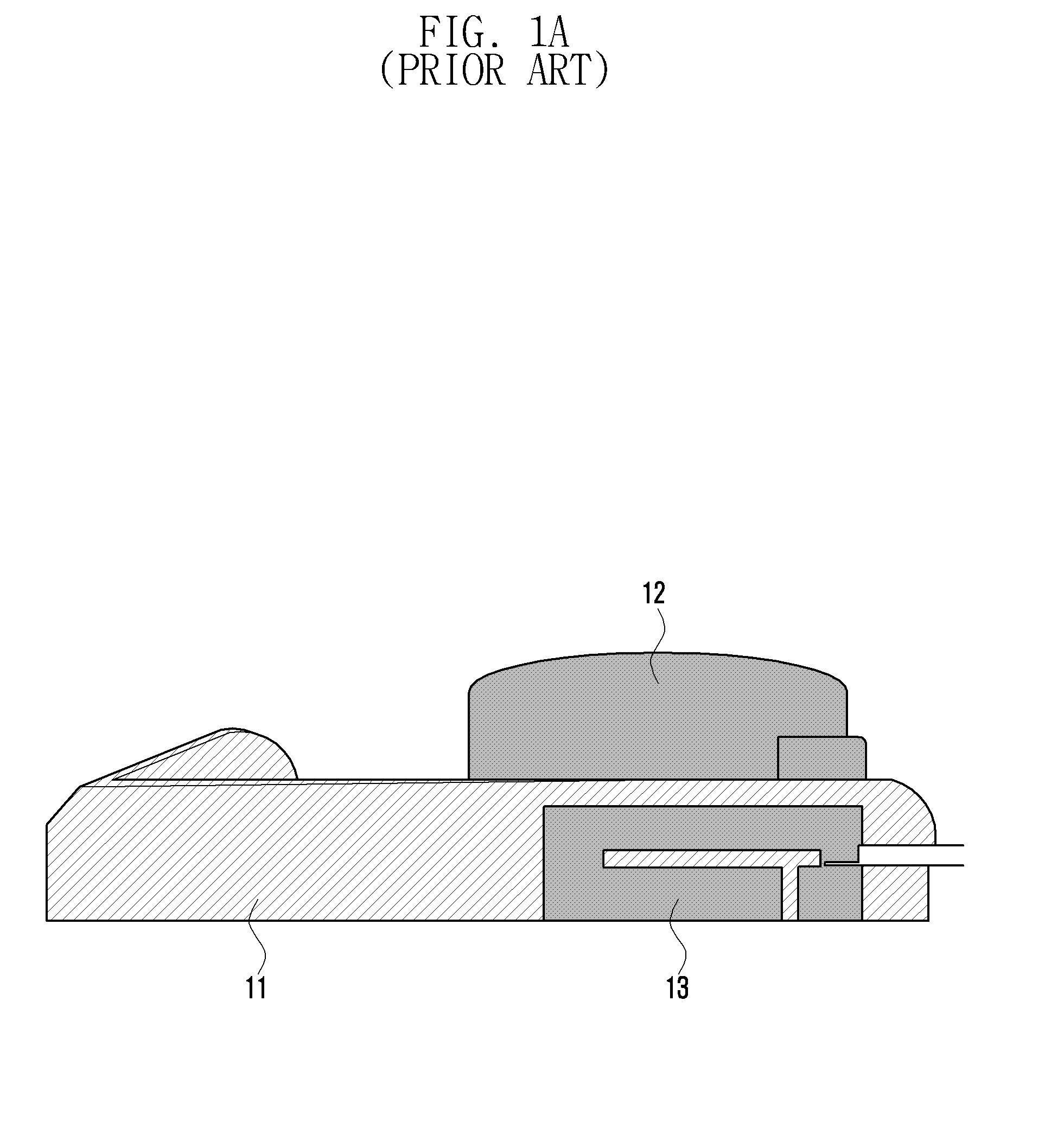
However, it is difficult to ensure a space due to the influence of a power, a shutter, and a zoom.
The left or right side of the camera may affect the performance due to a hand effect, and the lower end portion of the camera may be affected by use of a tripod or a battery.
Further, due to the dispersed arrangement of the plurality of antennas, the efficiency of the internal layout of the camera is deteriorated, and this results in the miniaturization and slimming of the camera to be disturbed.

Method used


Image

  • Antenna for camera
  • Antenna for camera
  • Antenna for camera

Examples


Embodiment Construction

[0042]Hereinafter, embodiments of the present invention will be described in detail with reference to the accompanying drawings to the extent that those of ordinary skill in the art to which the present disclosure pertains can easily understand the description.

[0043]In the following description of the present invention, a detailed description of the technical contents that are well known in the technical field, to which the present disclosure pertains, and are not directly related to the present invention will be omitted. By omitting such an unnecessary description, the subject matter of the present invention will become quite clear.

[0044]For the same reason, in the drawings, some constituent elements are exaggerated, omitted, or schematically illustrated. Further, the sizes of the respective constituent elements may not entirely reflect the actual sizes. In the entire description of the present invention, the same drawing reference numerals are used to refer to the same constituent...


PUM


Abstract

An antenna for a camera, comprising a camera having a communication module provided therein, a first radiator provided in a predetermined position of a lens barrel of the camera and having a length and a width for receiving a signal from a first wireless communication system, a power feeding line configured to feed a power from the communication module of the camera to the first radiator, and a ground line configured to ground the first radiator.

Description

PRIORITY[0001]This application claims priority under 35 U.S.C. §119(a) to a Korean patent application filed on Feb. 27, 2013 in the Korean Intellectual Property Office and assigned Serial No.10-2013-0020827, the entire disclosure of which is incorporated herein by reference.BACKGROUND OF THE INVENTION[0002]1. Field of the Invention[0003]The present disclosure generally relates to an antenna for a camera, and more particularly, to an antenna for a camera that is accommodated in a lens barrel, which is detachably attached to the camera to zoom out, to adjust resonance frequencies.[0004]2. Description of the Related Art[0005]In general, a digital camera is a device that converts light reflected from an object into an electrical signal, stores the converted electric signal as image data, and processes or reproduces the stored image data.[0006]Since the digital camera does not use a film, development, photo printing, and / or enlargement processes are not required, and both a still image a...

Claims


Application Information

Patent Timeline
Patent Type & Authority Applications(United States)
IPC IPC(8): H04N5/225
CPCH04N5/2251G03B17/02G03B2217/002H01Q1/242H01Q9/145H01Q9/42H01Q13/10H01Q21/28H01Q5/378H01Q5/40
Inventor SUNG, SANGBONGKIM, SEUNGHWANBYUN, JOONHOCHUN, JAEBONG
Owner SAMSUNG ELECTRONICS CO LTD
Learn More