
Apparatus for Very High Speed Adaptive Spectrum Analysis

a spectrum analysis and adaptive technology, applied in the field of apparatus for very high-speed adaptive spectrum analysis, can solve the problems of inability to meet the needs of users, inability to accurately identify signals, and many disadvantages, and achieve the effects of quick identification of signals, quick narrowing of signals, and quick verification of signals dynamically

Inactive Publication Date: 2014-08-28
BASAWAPATNA GANESH RAMASWAMY +3
View PDF9 Cites 22 Cited by
  • Summary
  • Abstract
  • Description
  • Claims
  • Application Information

AI Technical Summary

Benefits of technology

The invention recognizes that the process of preselection, which is a filter-tuning process, slows down the speed of measurement and is dependent on the characteristics of the preselector filter. The invention eliminates the need for preselection in spectrum analyzers and introduces a new function called Adaptive Sweep that allows for faster verification of signals in mid sweep and simultaneous processing with multiple resolution bandwidths. This new method provides faster speed, lower cost, and smaller size, making it ideal for creating handheld solutions for signal analysis.

Problems solved by technology

Unfortunately, the creation and existence of multiple harmonics of the signal and LO frequency within the mixer implies that there is the mathematical possibility that for some other values of n and m, n·Fsig mixing with m·Flo creates a signal at Fif.
This is not acceptable as it can produce a spurious signal display at a frequency where there is no actual signal present at the input.
The disadvantages unfortunately are many.
Their linearity is not perfect.
They suffer from significant thermal drift.
This severely limits the speed with which the YIG devices can be tuned to different frequencies.
In a spectrum analyzer, where the LO and preselector filter need to exactly track each other within the first IF bandwidth, these drifts impose significant other constraints.
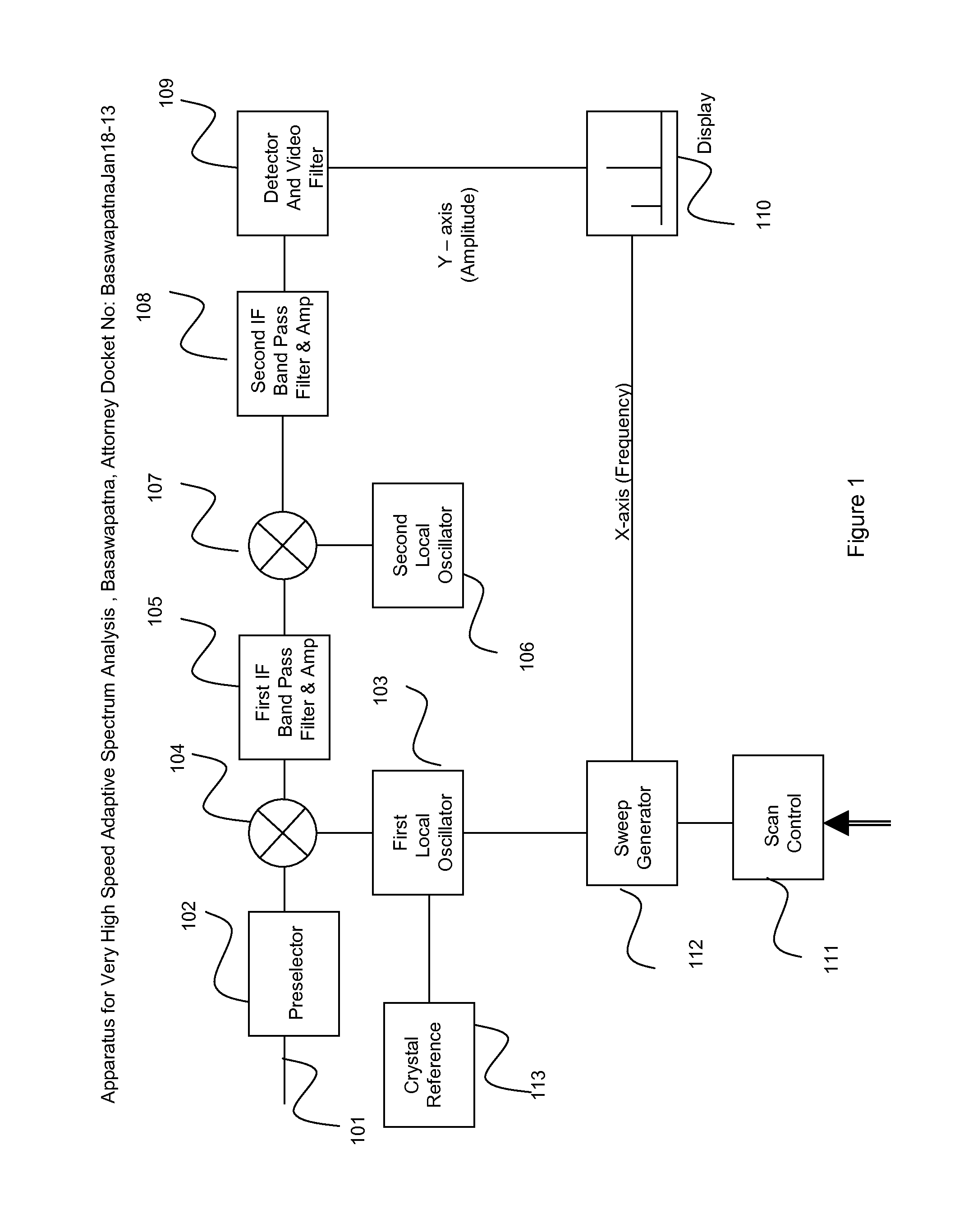
Another very difficult constraint is that while the YTO can indeed be phase locked or synthesized to any accuracy its crystal reference, 113, in FIG. 1, provides, the YTF, being essentially open loop, cannot have such accuracy.
As a result, in YIG tuned spectrum analyzers, except for the start of a sweep, the first LO is never phase locked or accurate as a locked oscillator.
The problem with this solution is that if one wanted to build a broadband analyzer covering many decades of frequency range, many microwave filters would be required, along with banks of microwave switches.
This is a very expensive and almost impractical solution.
As a result this is not a method that is used except in specific narrow bandwidth instruments for very specialized applications.
The problem with this method is that the IF is really a DC or close to DC value, which requires to sweep the signal very slowly, and is not usable even in moderate bandwidth receivers.
They are very impractical in broadband receivers.
Another problem with these traditional approaches is that, to identify the existence of signals in the frequency range of interest and then to analyze the modulation, phase noise, or other characteristics of the spectra, multiple sweeps are needed.
Since, due to YIG tuning speed limitations, each sweep is typically several hundred milliseconds in duration, any measurement that takes multiple sweeps will take many seconds to complete.
In an agile signal environment for example in Electronic Warfare this is not be acceptable.

Method used


Image

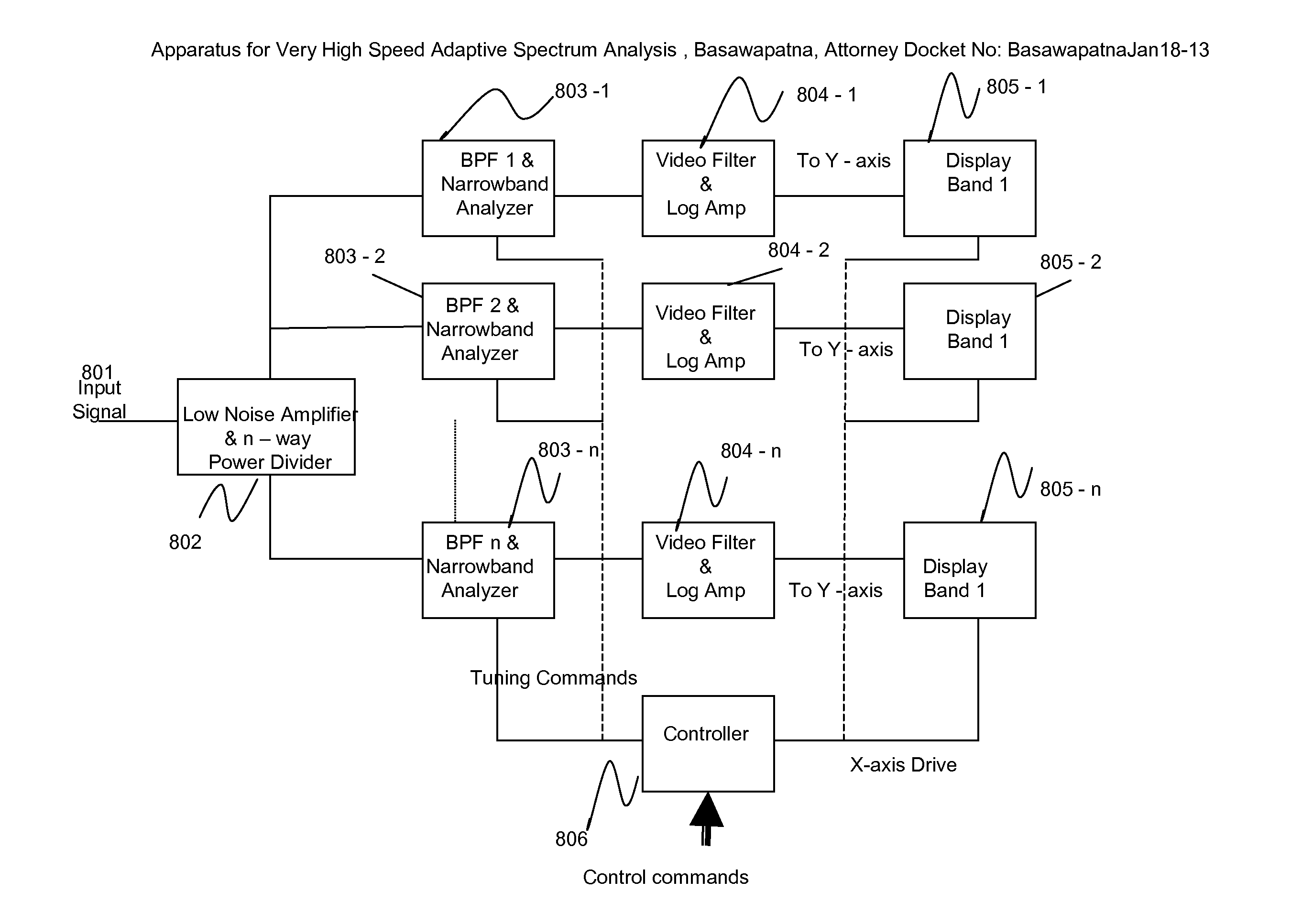
  • Apparatus for Very High Speed Adaptive Spectrum Analysis
  • Apparatus for Very High Speed Adaptive Spectrum Analysis
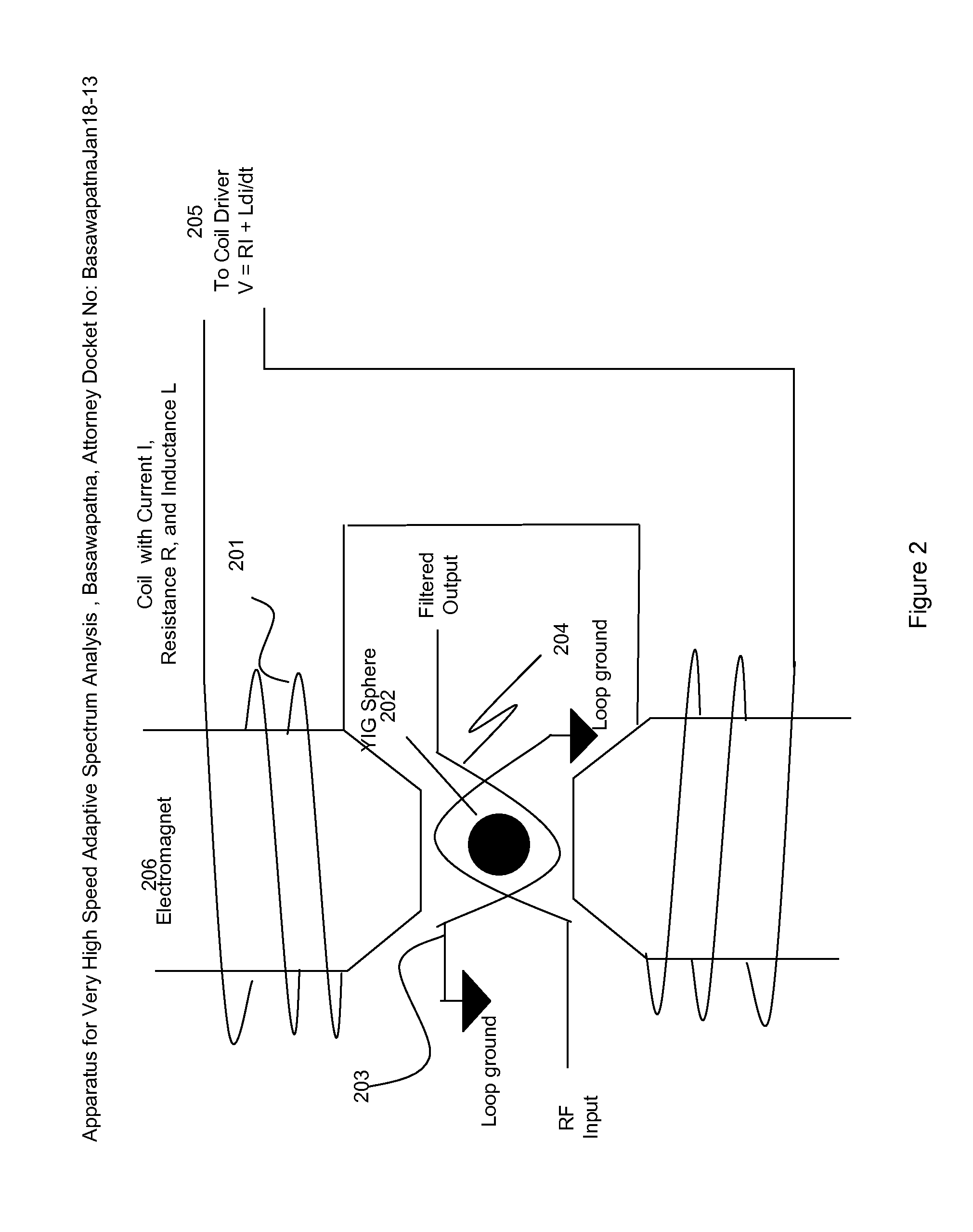
  • Apparatus for Very High Speed Adaptive Spectrum Analysis

Examples


Embodiment Construction

[0034]The invention concepts are described in this section using the drawings referred to. They do not represent all possible embodiments, but are used primarily for illustrative purposes.

[0035]The proposed instrument block diagram is shown in simplified form in FIG. 3. The input signal 301 at frequency Fin is split into two equal signals at the splitter 302. One half of the signal is input to Mixer1, 305 and the other half to Mixer 2, 306. The local oscillator 307 for Mixer 1 is at a frequency Flo+Δf, and the local oscillator 309 for Mixer 2 is at frequency Flo−Δf. The value of Δf is kept constant and Flo is varied linearly with time from start frequency to some stop frequency, which define the region of interest for incoming signals. Both the local oscillators at Flo+Δf and at Flo−Δf are frequency synthesized at every point in the sweep and are controlled by the same crystal reference 308, so that they are exactly 2Δf apart in frequency. The offset Δf can be a very small offset, f...


PUM


Abstract

This invention describes a method by which Broadband Spectrum Analysis can be performed in the Rh and Microwave frequency range with significantly higher speed, accuracy, and flexibility than existing RF and Microwave Spectrum Analyzers. This is done by eliminating the need for the filtering of the incoming signal, a process called preselection that needs to track in frequency with the scanning local oscillator in the instrument. By eliminating this requirement, this invention makes possible the identification and analysis of very broadband signals in a single sweep using an Adaptive Sweep Methodology and a Simultaneous Sweep capability that the present invention makes possible.

Description

FIELD OF THE INVENTION[0001]This invention pertains to a method to create the ability to analyze RF and microwave signals via a new form of spectrum analyzer.DEFINITION OF TERMS[0002]Local Oscillator (LO): When a signal frequency is desired to be translated to another frequency a Local Oscillator is used in conjunction with a mixer to create the Intermediate Frequency (IF).[0003]Mixer: When two frequencies, F1 and F2 are input to two ports of a mixer, it typically generates ±m·F1±n·F2, frequencies, where m and n are integers.[0004]Intermediate Frequency (IF): All the resultants of the mixing process in the above paragraph are called Ifs. In particular, frequencies generated with m=n=1 are most often used in Fundamental Mixing.[0005]IF Bandwidth: The bandwidth of the filter, which is typically a band-pass filter that follows the mixer and selects only the desired IF.[0006]Video Detector: A device that creates a DC voltage proportional to the amplitude of the RF or IF signal applied t...

Claims


Application Information

Patent Timeline
Patent Type & Authority Applications(United States)
IPC IPC(8): H04N17/04H04N5/44
CPCG01R23/00G01R23/165G01R23/14
Inventor BASAWAPATNA, GANESH RAMASWAMYBASAWAPATNA, VARALAKSHMIBASAWAPATNA, ANAND GANESHBASAWAPATNA, ASHOK RAM
Owner BASAWAPATNA GANESH RAMASWAMY
Learn More