Container crane, and method of determining and correcting a misalignment between a load-carrying frame and a transport vehicle

a technology of container crane and load-carrying frame, which is applied in the field of container crane, can solve problems such as adversely affecting container transshipment, and achieve the effect of large scanning area and large recording area

Active Publication Date: 2007-10-30
SIEMENS AG
View PDF18 Cites 33 Cited by
  • Summary
  • Abstract
  • Description
  • Claims
  • Application Information

AI Technical Summary

Benefits of technology

[0008]When an offset or rotation angle is known, the spreader can be shifted relative to the head block by a suitable adjustment mechanism, primarily adjustment cylinders, operated by a control unit. In other words, the spreader is slightly moved lengthwise and / or transversely and / or turned relative to the head block to compensate the offset or rotation angle as detected through a comparison of the center lines. The edge detection and determination of an offset or rotation angle takes place immediately after the trolley has been positioned above the transport vehicle. In other words, the position of the load-carrying frame is rapidly verified and a misalignment is respectively corrected. Any positional inaccuracy can be quickly identified and corrected in a fully automated manner because edge detection and determination of the offset or rotation angle takes place automatically as is the adjustment of the spreader relative to the head block with the assistance of the suitable control unit which receives respective data with respect to offset or rotation angle from the processing unit.
[0015]According to another feature of the present invention, the processing unit may be constructed for determining a tilt of the transport vehicle in relation to a horizontal plane. This is especially opportune, when, for example, a tire of the transport vehicle is flat or the tire pressure is too low so that the support surface of the transport for a container is slightly inclined. As a result, the disposition of the edge and thus the course of the center lines change, whereby the extent of the change depends on the size of the tilt angle. A potential error resulting from a tilt can thus be recognized and corrected. A tilt of the transport vehicle may, of course, also be caused by an uneven ground. If a possible skew is known, the load center, i.e. the center of the load-carrying frame and thus also of an pendantly connected container, can be corrected by the skew in length and transverse directions in relation to the center of the transport vehicle as well as a possible angle between the length and / or transverse lines.
[0017]According to another feature of the present invention, each laser scanner may be constructed to radiate a laser beam in a cone-beam shape at a beam angle between 2° and 8°, especially 4°. The laser scanners are positioned relatively high, as the trolley travels at a height of greater than 20 m, so that a large enough scanning area of the load-carrying frame is realized, when the load-carrying frame is quasi lowered through the cone-beam radiation, and of the transport vehicle at ground level. This ensures a continuous detection of the transverse and longitudinal edges of the load-carrying frame and the transport vehicle. Likewise, when cameras are used as detectors, the cameras can be constructed to establish also a large enough recording area.
[0018]According to another feature of the present invention, a tilt sensor may be operatively connected to the processing unit for determining a tilt of the boom, whereby the processing unit is constructed to take into account the tilt of the boom when determining the presence of an offset between the longitudinal and transverse center lines of the head block or spreader and the longitudinal and transverse center lines of the transport vehicle, as well as the presence of a rotation angle of the center lines. The boom, along which the trolley travels, may tilt over time so that the trolley will no longer travel precisely in the horizontal plane but along a respectively inclined track. As a result, the detectors tilt as well and record the transverse and longitudinal edges at an angle which deviates from the original calibration. In other words, the calculation of the disposition of the transverse differs. By using the tilt sensor, a possible tilt of the boom and of the detectors can be detected and suitably compensated.
[0020]According to another feature of the present invention, a control unit may be provided to control a hoisting operation of the trolley, whereby the control unit provides information about a lifting height of the head block or the spreader and communicates with the processing unit such that the processing unit considers the information upon determination of the possible offset and / or rotation angle. On the basis of the actual height, the processing unit is able to determine at which height information can be expected about the head block or spreader edges. By using a filter, furnished image data or image signals from the detectors, can be filtered to suppress image data artifacts or signal artifacts in dependence on the lifting height of the head block or the spreader. For example, when an image data artifact or signal artifact indicates the presence of an edge in a region above the actual lifting height of the head block, the indication of the edge can be ignored or simply interpreted as an error that does not require any further processing. In other words, a data or signal filtering measure is provided that allows elimination of error interpretations in a simple manner.

Problems solved by technology

This course of action is not only imprecise and depends primarily on the competence of the crane operator to recognize a positional difference, e.g. an offset, and to execute proper correction through operation of the lifting gear or the running gear, but is also time-consuming, thus adversely affecting the container transshipment.

Method used


Image

  • Container crane, and method of determining and correcting a misalignment between a load-carrying frame and a transport vehicle
  • Container crane, and method of determining and correcting a misalignment between a load-carrying frame and a transport vehicle
  • Container crane, and method of determining and correcting a misalignment between a load-carrying frame and a transport vehicle

Examples


Embodiment Construction

[0032]Throughout all the Figures, same or corresponding elements are generally indicated by same reference numerals. These depicted embodiments are to be understood as illustrative of the invention and not as limiting in any way. It should also be understood that the drawings are not necessarily to scale and that the embodiments are sometimes illustrated by graphic symbols, phantom lines, diagrammatic representations and fragmentary views. In certain instances, details which are not necessary for an understanding of the present invention or which render other details difficult to perceive may have been omitted.

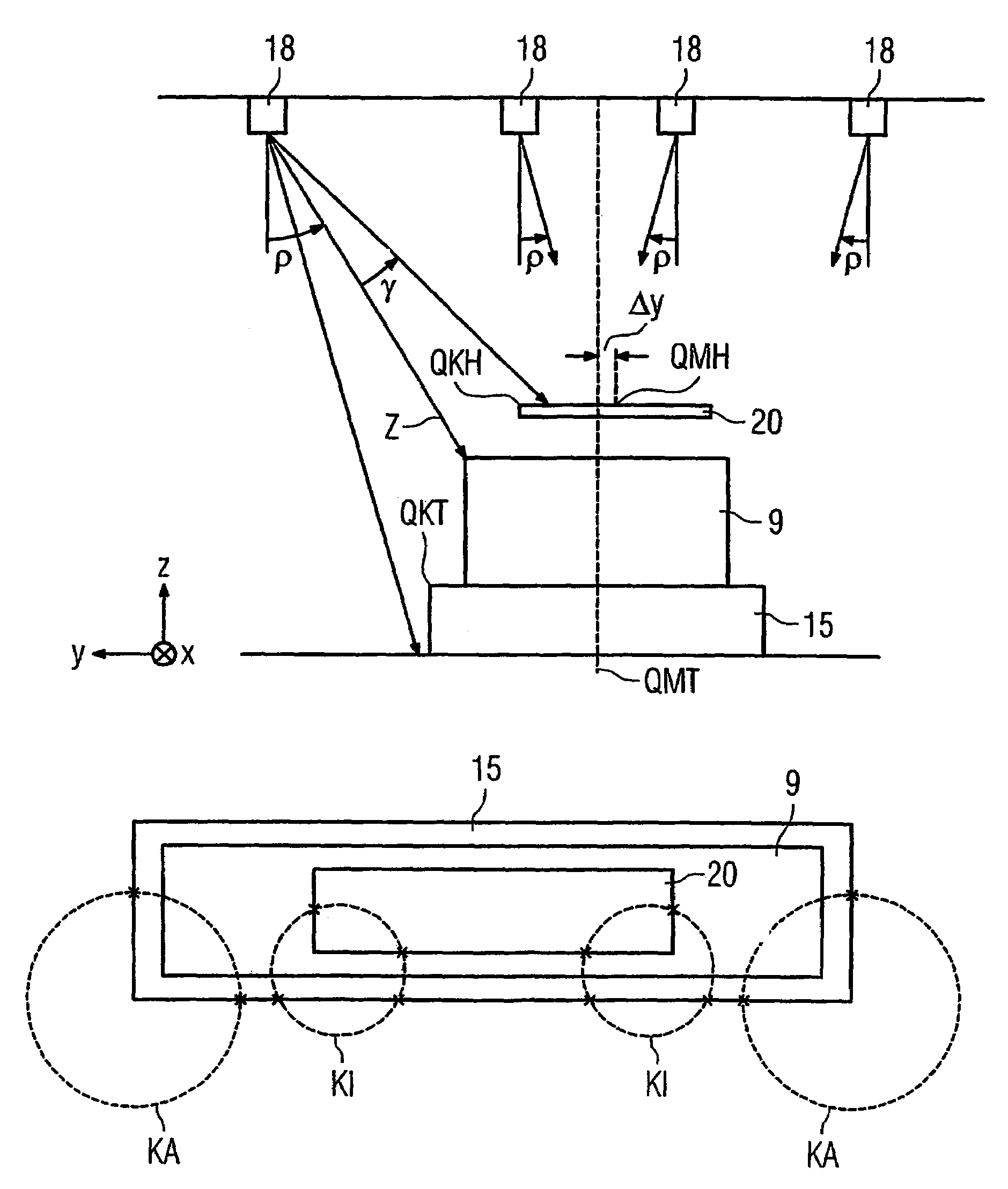
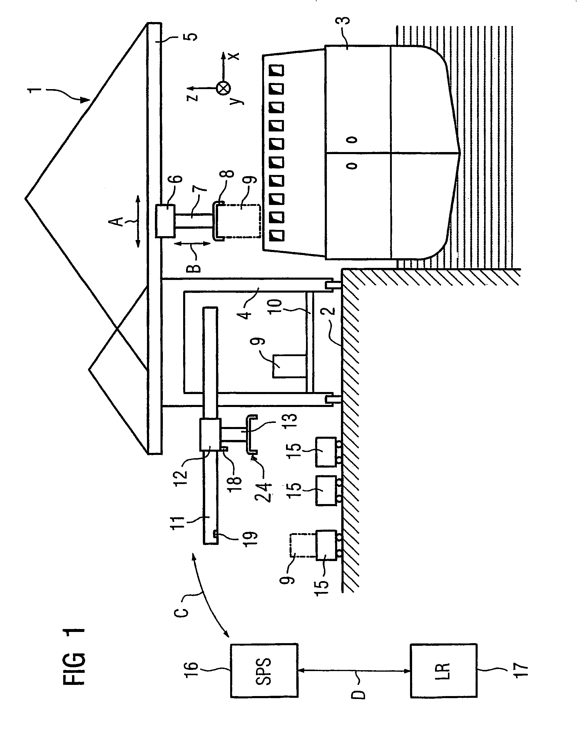
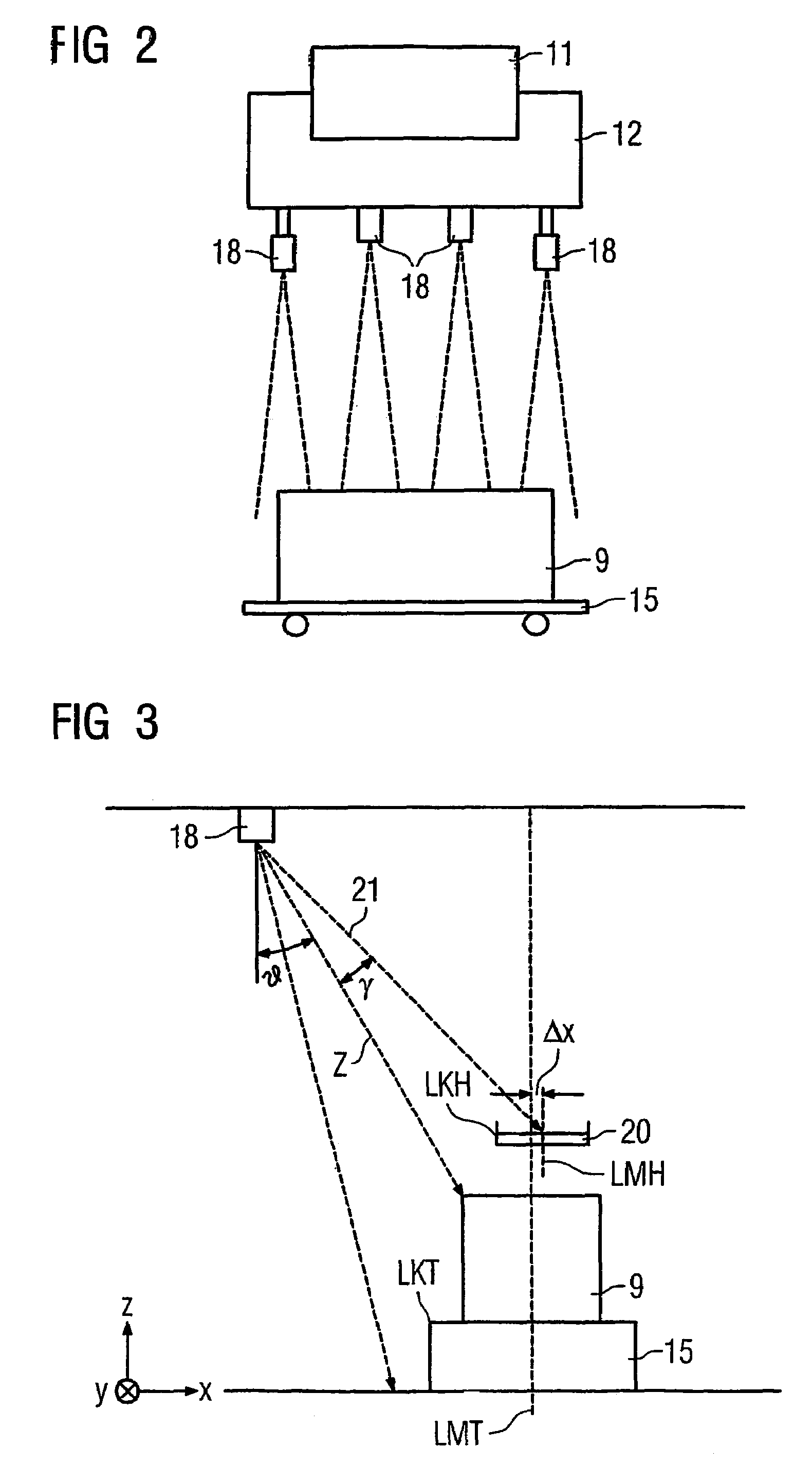
[0033]Turning now to the drawing, and in particular to FIG. 1, there is shown a principal illustration of a container crane according to the present invention in the form of a two-trolley container bridge, generally designated by reference numeral 1 and moveable by a traveling gear along a quay wall 2 in length direction of a container ship 3. The container crane 1 includes a ...


PUM


Abstract

A container crane includes a movable trolley and a load-carrying frame pendantly connected to the trolley and comprised of a spreader and a head block, for transfer of a container from or to a transport vehicle. Plural optical detectors are mounted on the trolley for identifying longitudinal and transversal edges of the head block or spreader and the transport vehicle. Operatively connected to the detectors is a processing device for determining a spatial position of the edges and calculating a position of longitudinal and transversal center lines of the head block or spreader and the transport vehicle and their spatial positions in relation to one another. In this way a possible offset of the center lines of the head block or spreader with regard to those of the transport vehicle in longitudinal and transversal directions as well as a rotation angle of the center lines can be determined, whereby a detected offset or rotation angle is compensated by displacing the spreader relative to the head block.

Description

CROSS-REFERENCES TO RELATED APPLICATIONS[0001]This application is a continuation of prior filed copending PCT International application no. PCT / DE2003 / 003506, filed Oct. 21, 2003, which designated the United States and on which priority is claimed under 35 U.S.C. §120, and which claims the priority of German Patent Application, Serial No. 102 51 910.2, filed Nov. 7, 2002, pursuant to 35 U.S.C. 119(a)-(d).BACKGROUND OF THE INVENTION[0002]The present invention relates, in general, to a container crane, and more particularly to a container crane having a system for determining and correcting a relative position of a load-carrying frame to a transport vehicle.[0003]Nothing in the following discussion of the state of the art is to be construed as an admission of prior art.[0004]A container crane of a type involved here is used for loading and unloading container ships and typically includes a trolley that is movable along a boom and has a hoist mechanism with suspended load-carrying fram...

Claims


Application Information

Patent Timeline
Patent Type & Authority Patents(United States)
IPC IPC(8): G06F7/00B66C13/08B66C13/46
CPCB66C13/46B66C13/085
Inventor LUSSEN, SVENSPARENBORG, ERNSTTSCHIERSE, KARL-HEINZWOBSE, STEPHAN
Owner SIEMENS AG
Why Eureka
Try Eureka