Refrigeration mechanical diagnostic protection and control device

a technology of mechanical diagnostic and control device, which is applied in the direction of cooling fluid circulation, domestic cooling apparatus, lighting and heating apparatus, etc., can solve the problems of loss of lubricating oil, excessive high discharge temperature, and high cost of compressor failure, so as to increase system efficiency, reduce subcooling, and increase subcooling

Inactive Publication Date: 2006-04-13
TRACEY GEORGE R JR +2
View PDF21 Cites 29 Cited by
  • Summary
  • Abstract
  • Description
  • Claims
  • Application Information

AI Technical Summary

Benefits of technology

[0024] In addition to system protection from low superheat, the present invention uses the collected data to further increase system efficiency by providing a method of increasing subcooling under heavy load conditions or decreasing subcooling when needed.
[0025] An electrical device monitors the mechanical aspects of standard refrigeration and air conditioning systems. The device protects these systems by calculating temperature, pressure, superheat, sub-cooling, ambient temperature and controlling system components. The device provides an easy, graphic representation of system conditions and faults for rapid verification of satisfactory operating parameters. Further detailed system conditions are provided for more extensive examination through use of digital read-outs.

Problems solved by technology

The failure of a compressor is usually very costly.
Most compressor failures can be traced back to one of the following system conditions: “refrigerant floodback”, “flooded starts”, “slugging”, excessively high discharge temperature or loss of lubricating oil.
The lubricant oil becomes mixed with refrigerant to the point that it cannot properly lubricate the load bearing surfaces.
When the compressor starts, the diluted oil cannot properly lubricate the load bearing surfaces causing erratic wear.
In the case of excessively high discharge temperature the compressor head and cylinders become so hot that the oil loses its ability to lubricate properly.
This causes rings, pistons and cylinders to wear resulting in “blow by”, leaking valves and metal debris in the oil.
Loss of oil is the result of insufficient oil in the crankcase to properly lubricate the load bearing surfaces.
The result is the system superheat.
Another cause for concern is introduction of foreign materials from the gauge set into the system.
This device does not monitor or display other system parameters such as temperature and pressure.
Further it does not provide simple system status indicators for the actual condition of superheat.
This device also relies on analog to digital converters for refrigerant pressure sensing, a method with inherent inaccuracies that would not provide the level of accurate control required with a refrigeration system under heavy load conditions.
These devices, however, only address one or two dangerous systems conditions and fail to provide and adequate level of compressor protection.

Method used


Image

  • Refrigeration mechanical diagnostic protection and control device
  • Refrigeration mechanical diagnostic protection and control device
  • Refrigeration mechanical diagnostic protection and control device

Examples


Embodiment Construction

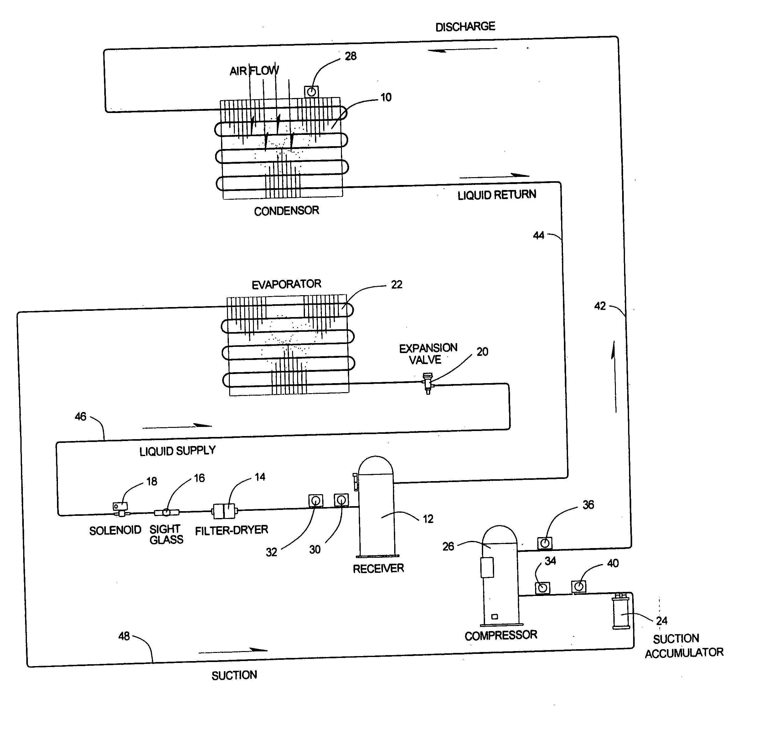
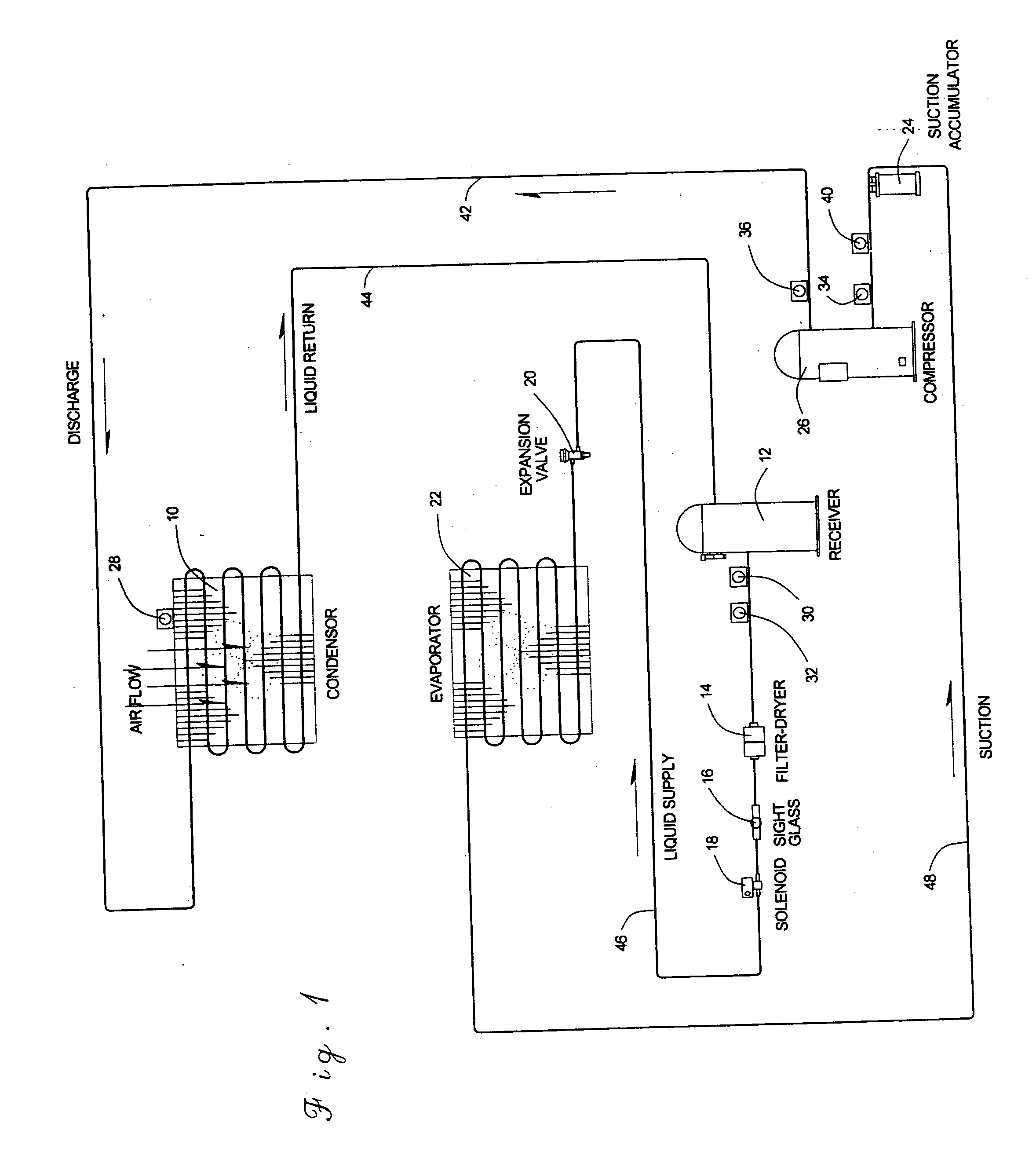
[0035] Referring in more particularity to the drawings, FIG. 1 illustrates a diagram of a standard refrigeration system which includes a compressor 26 driven by an electric motor in a conventional manner. The discharge side of the compressor 26 connects with a discharge line 42 which delivers the compressed refrigerant in a gaseous state to a condenser 10 or in some systems multiple condensers. Near the outlet of the compressor 26 a discharge temperature sensor 36 is connected with the discharge line 42. The gaseous refrigerant condenses into a liquid state in the condenser 10. Located at the inlet air side of the condenser 10 is an outdoor temperature sensor 28.

[0036] Exiting the condenser 10, the liquid refrigerant travels in the liquid line 44 to a receiver 12 which stores excess refrigerant during low load conditions.

[0037] Exiting the receiver 12 the refrigerant travels through the liquid line 46. Located on the supply line 46 near the exit of the receiver 12 are a high press...


PUM


Abstract

In vapor compression refrigeration systems a mechanism and method are provided for protecting a compressor from failures related to lack of superheat, loss of lubricating oil and other system malfunctions. Also provided is a mean of monitoring system conditions and providing service personnel with a quick manner of diagnosing problems.

Description

BACKGROUND OF THE INVENTION [0001] The present invention relates to refrigeration, air conditioning and heat pumps and more particularly to a method and apparatus for monitoring and controlling system pressures, temperatures, and superheat and subcooling. [0002] In the operation of refrigeration and air conditioning systems, the cooling effect is provided by the change in state of the refrigerant from a liquid to a gas in the evaporator of the system. The gaseous refrigerant is compressed by a compressor and is condensed to a liquid state in a condenser before passing through an expansion valve upon being returned to the evaporator. [0003] The failure of a compressor is usually very costly. Most compressor failures can be traced back to one of the following system conditions: “refrigerant floodback”, “flooded starts”, “slugging”, excessively high discharge temperature or loss of lubricating oil. [0004]“Refrigerant floodback” results when liquid refrigerant returns to the compressor ...

Claims


Application Information

Patent Timeline
Patent Type & Authority Applications(United States)
IPC IPC(8): F25D17/00F25B41/04F25B1/00F25B49/00F25B39/04
CPCF25B49/005F25B49/027F25B2339/041F25B2500/19F25B2600/111F25B2600/19F25B2600/21F25B2700/1931F25B2700/1933F25B2700/2106F25B2700/2108F25B2700/21151F25B2700/21152F25D2400/36Y02B30/743Y02B30/70
Inventor TRACEY, GEORGE R. JR.SULLIVAN, SHAWN P.HOLSTEIN, GEORGE L.
Owner TRACEY GEORGE R JR
Why Eureka
Try Eureka