Supercharge Your Innovation With Domain-Expert AI Agents!

Method for Calibrating the Position of the Slitter Blades of a Slitter-Winder

a technology of slitter blades and slitterwinders, which is applied in the direction of scientific instruments, measurement devices, instruments, etc., can solve the problems of slitter blade edge wear and other problems, and achieve the effect of convenient use and reliable operation methods

Active Publication Date: 2014-08-28
VALMET TECH INC
View PDF10 Cites 9 Cited by
  • Summary
  • Abstract
  • Description
  • Claims
  • Application Information

AI Technical Summary

Benefits of technology

The invention provides a method for calibrating the positions of slitter blades in a fiber web production line that uses a laser. This is done while the slitter is in standstill and there is no fiber web running or being slit between the slitter blades. The laser measurement is done at the fiber web cutting point of a slitter blade, and the calibration is used to calibrate the slitter blade carriage position sensors. A laser beam is directed to the slitter blade to ensure accuracy in measuring its position. This method ensures consistent and accurate calibration of the slitter blades, which improves the quality and efficiency of the production process.

Problems solved by technology

The slitter blade edge also wears, which leads to inaccuracy when using the above-mentioned measurement methods.

Method used


Image

  • Method for Calibrating the Position of the Slitter Blades of a Slitter-Winder
  • Method for Calibrating the Position of the Slitter Blades of a Slitter-Winder
  • Method for Calibrating the Position of the Slitter Blades of a Slitter-Winder

Examples


Embodiment Construction

[0028]During the course of this description like numbers and signs will be used to identify like elements according to the different views which illustrate the invention.

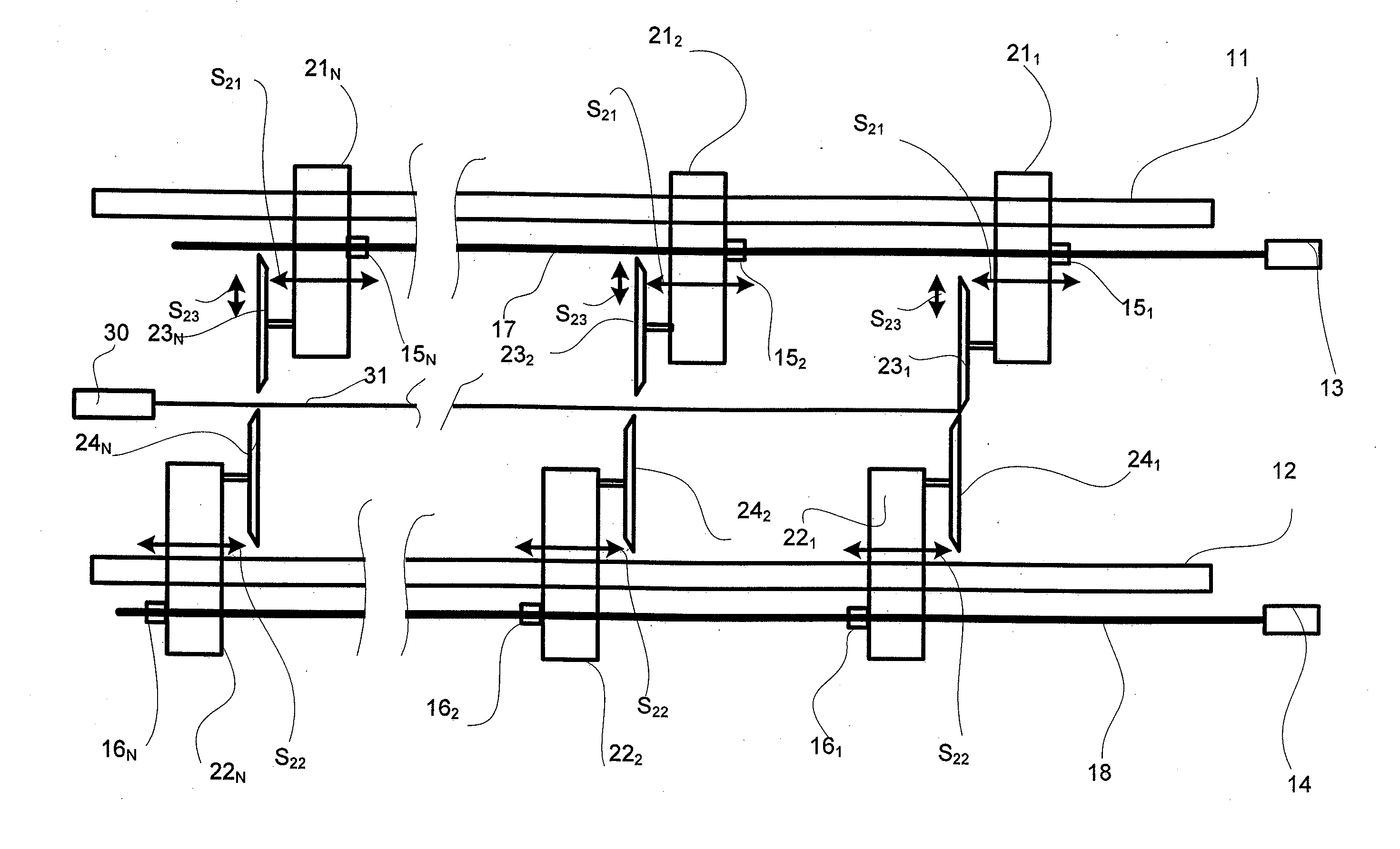
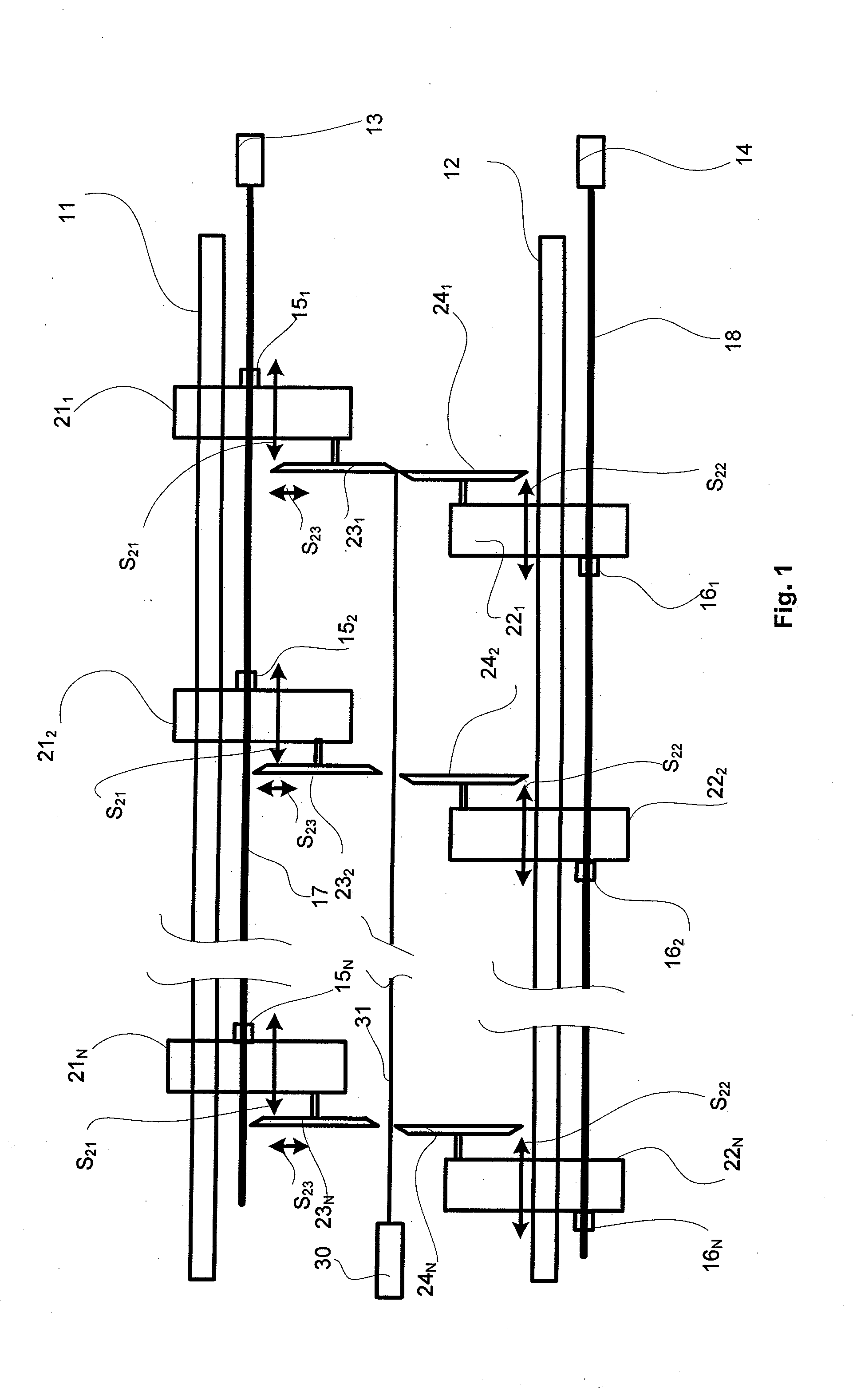
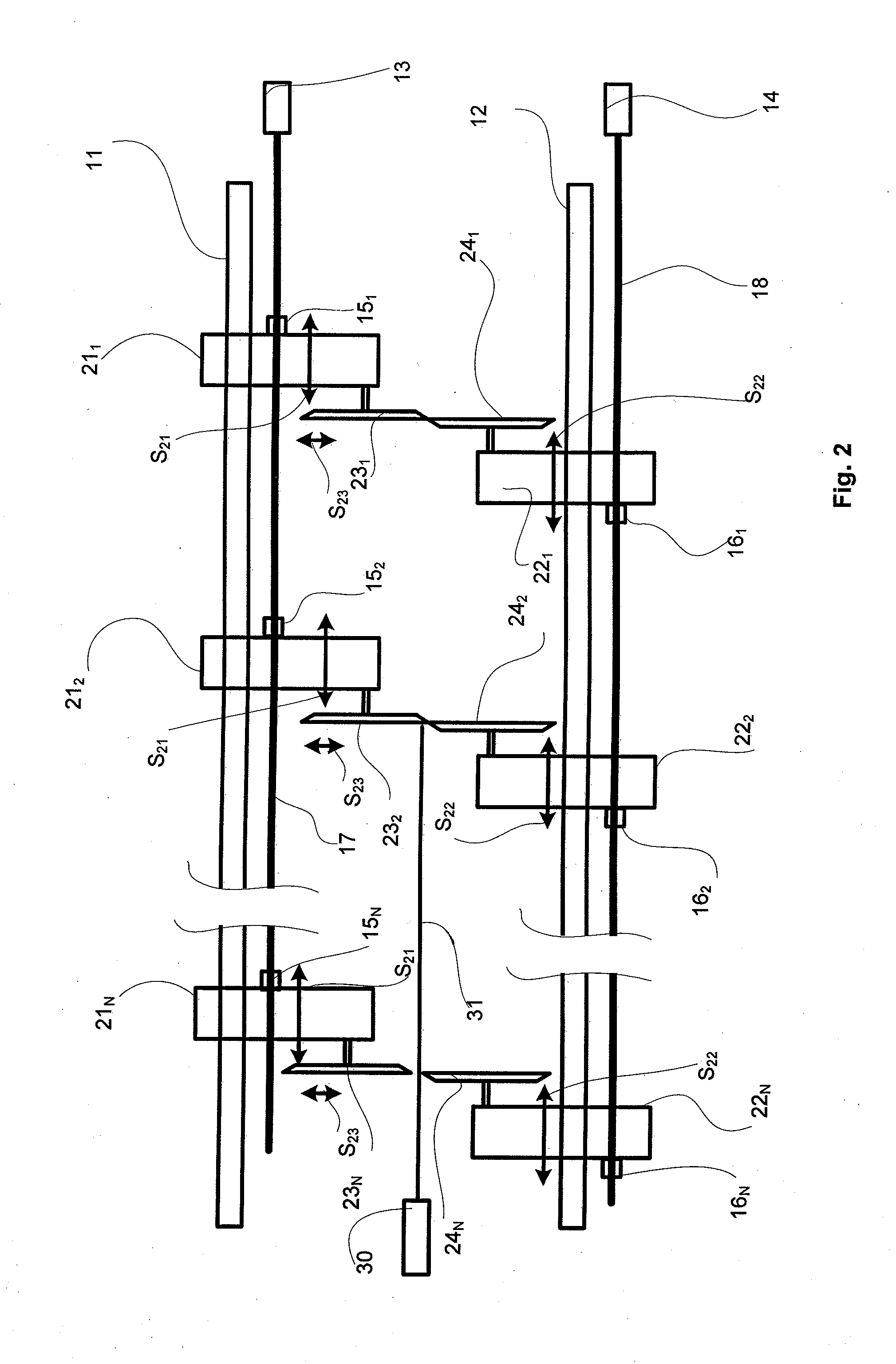
[0029]FIGS. 1-3 show three of the top blades 231, 232, 23N and bottom 241, 242 2, 24N slitter blade pairs used in slitting. Typically there are 15-25 pairs of slitter blades in a slitter for slitting the fiber web longitudinally into partial webs in accordance with the desired widths of customer rolls (partial web rolls) to be produced in the slitter-winder. Each of the top slitter blades 231, 232, 23N is attached to a top slitter blade carriage 211, 212, 21N, correspondingly, which top slitter blade carriages 211, 212, 21N are arranged to be movable in a cross machine direction as shown by arrows S21 in relation to the travel direction i.e., the machine direction, of the web along an upper guide 11, and each of the bottom slitter blades 241, 242 2, 24N are attached to a bottom slitter blade carriage 221, 222, 22N, ...


PUM


Abstract

The positions of the slitter blades of a slitter-winder are calibrated using a laser to perform measurement and calibration of the fiber web cutting point of each slitter blade pair. Measurement and calibration is preformed on the top slitter blade of each of a multiplicity of slitter blade pairs one after another. The laser measures one slitter blade of each slitter blade pair while they are engaged. The slitter blade pairs between the laser and the slitter blade pair being measured are not engaged. Carriages which support the slitter blades have position sensors which the laser measurements calibrate and the blade pair positions are measured and the carriage positions are read simultaneously. The cutting edges of the slitter blades are sharpened to have straight sides and the laser measurement system is located so the laser beam is directed to the straight side.

Description

CROSS REFERENCES TO RELATED APPLICATIONS[0001]Not applicable.STATEMENT AS TO RIGHTS TO INVENTIONS MADE UNDER FEDERALLY SPONSORED RESEARCH AND DEVELOPMENT[0002]Not applicable.BACKGROUND OF THE INVENTION[0003]The present invention relates to a slitter-winder of a fiber web production line in general and in particular to a method for calibrating the position of the slitter blades of a slitter-winder.[0004]It is known that a fiber web, e.g. paper, is manufactured in machines which together constitute a paper-manufacturing line which can be hundreds of meters long. Modern paper machines can produce over 450,000 tons of paper per year. The speed of the paper machine can exceed 2,000 m / min and the width of the fiber web can be more than 11 meters.[0005]In paper-manufacturing lines, the manufacture of paper takes place as a continuous process. A fiber web completing in the paper machine is reeled by a reel-up around a reeling shaft, i.e. a reel spool, into a parent roll the diameter of whic...

Claims


Application Information

Patent Timeline
Patent Type & Authority Applications(United States)
IPC IPC(8): G01B21/16
CPCG01B21/16B26D1/245B26D7/2635
Inventor DAUL, MICHAEL J.
Owner VALMET TECH INC
Features
  • R&D
  • Intellectual Property
  • Life Sciences
  • Materials
  • Tech Scout
  • Unparalleled Data Quality
  • Higher Quality Content
  • 60% Fewer Hallucinations
Learn More