LED lighting device

Inactive Publication Date: 2014-08-28
BAE YOUNG SU +1
View PDF8 Cites 40 Cited by
  • Summary
  • Abstract
  • Description
  • Claims
  • Application Information

AI Technical Summary

Benefits of technology

[0042]According to the LED lighting device having the configuration as described above have the following advantageous effects.
[0043]A lamp heat sink having a radial structure is disposed on the rear side of LED light-emitting surfaces so as to be connected to a case body heat sink exposed to the outside to maximize the dissipation of heat generated from LED modules.
[0044]In addition, the case body heat sink is disposed to wholly or partially encircle the outer peripheral surface of the power case body to maximize the dissipation of heat generated from the LED module through the outer periphery of the case body heat sink.
[0045]In addition, the engagement structure between th

Problems solved by technology

However, the conventional lighting fittings entail problems in that their lifespan is short and much power is consumed, leading to an increase in energy cost, and in that the lighting fittings emit UV rays harmful to the human body or contain argon (Ar) gas, helium (He) gas and the like, causing a serious environmental issue.
In case of using LEDs as lighting fittings, however, there is involved a problem in that a heat dissipation structure of an LED lighting device is bulky and complicated due to high heat generated from the LEDs and light is not dispersed and diffused due to straightness of light emitted from the LEDs, causing a glare phenomenon.
Thus, there are still prob

Method used


Image

  • LED lighting device
  • LED lighting device
  • LED lighting device

Examples


Embodiment Construction

[0073]Now, preferred embodiments of a LED lighting device according to the present invention will be described hereinafter in detail with reference to the accompanying drawings.

[0074]Now, preferred embodiments of the present invention will be described hereinafter in detail with reference to the accompanying drawings. It should be noted that the same elements in the drawings are denoted by the same reference numerals although shown in different figures. In the following description, the detailed description on known function and constructures unnecessarily obscuring the subject matter of the present invention will be avoided hereinafter.

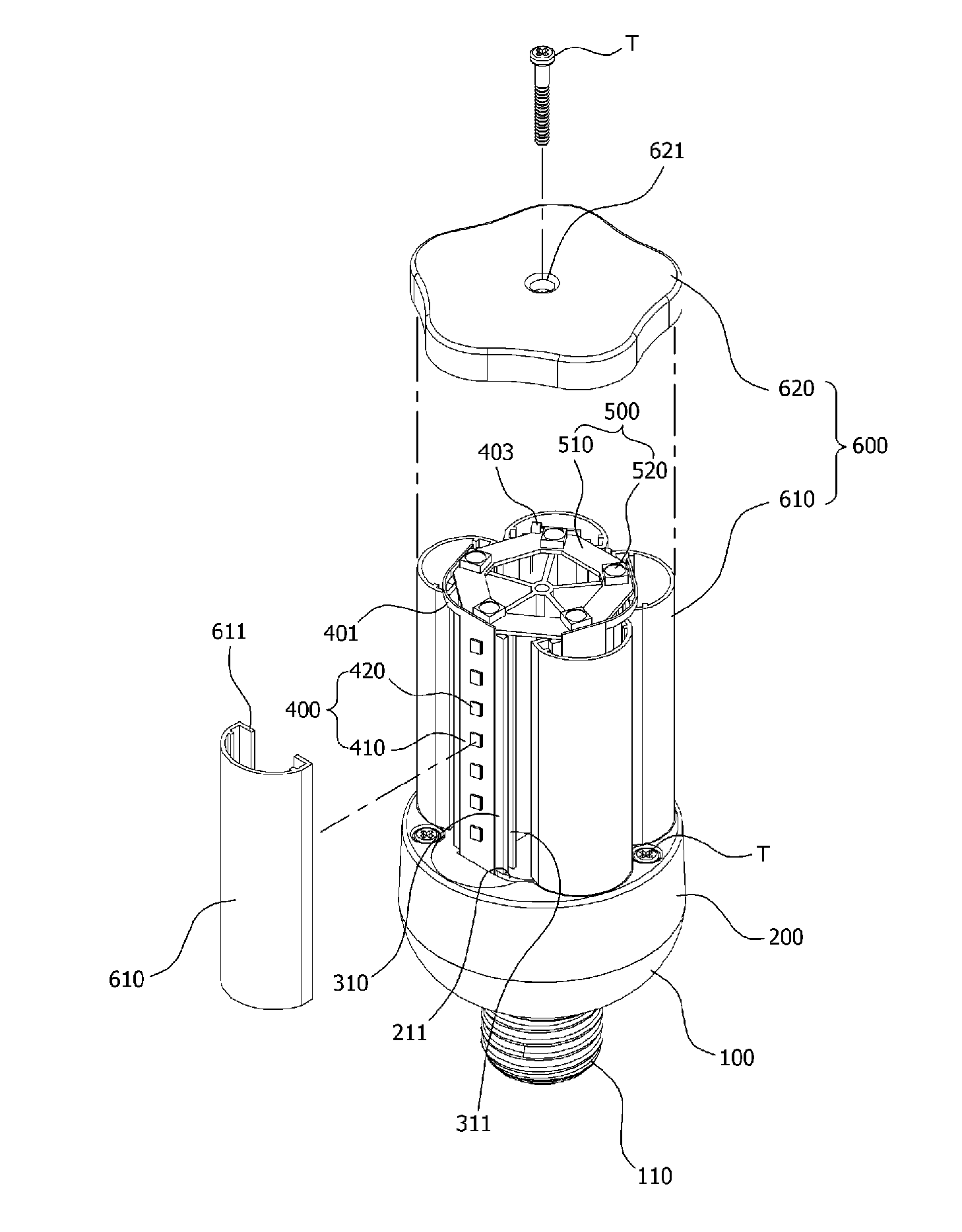
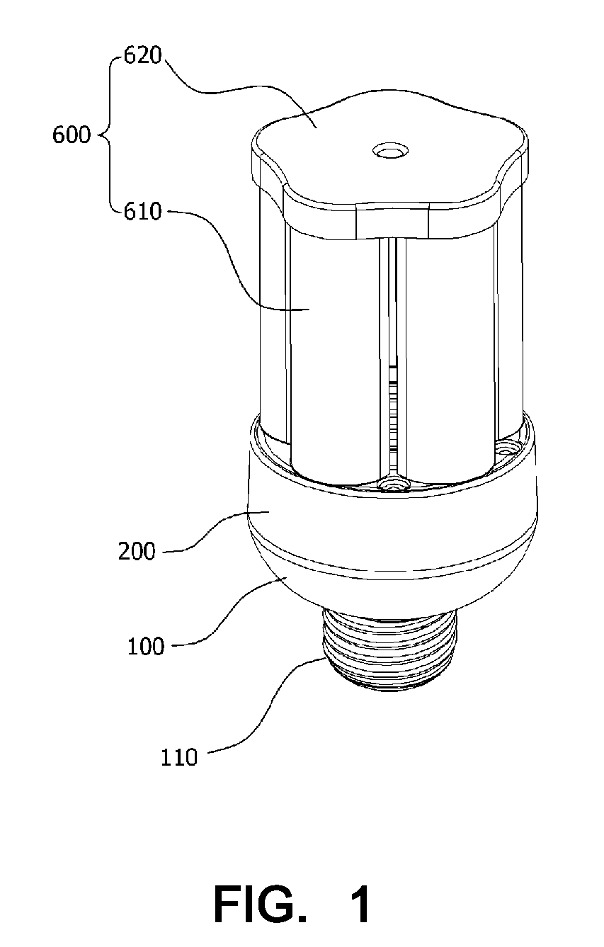
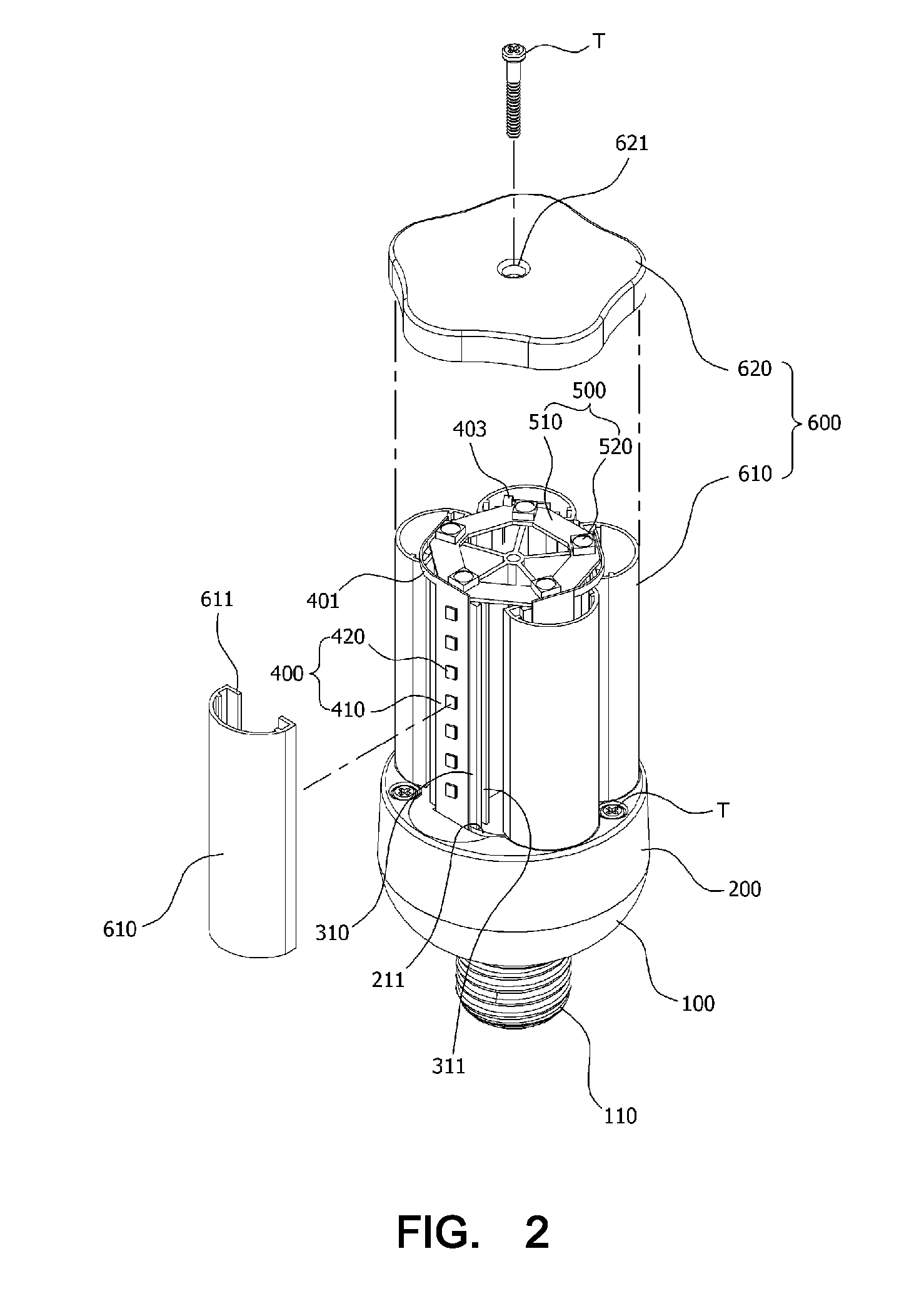
[0075]An LED lighting device according to one embodiment of the present invention is configured such that it has a sufficient light-emitting surface to allow light to be uniformly emitted to a wide area and simultaneously has a heat dissipation structure to prevent its damage due to generation of heat. The LED lighting device includes a power case bo...


PUM

PropertyMeasurementUnit
Transparencyaaaaaaaaaa
Heataaaaaaaaaa
Thermal conductivityaaaaaaaaaa

Abstract

The present invention relates to an LED lighting device comprising: a power case main body wherein one side is opened to form a receiving space inside, and a lamp terminal is provided to be electrically connected to a lamp socket on an end of the other side; a main body heat sink which surrounds a part or most of an outer circumference of the power case main body, and is combined to one side of the open power case main body; a plurality of lamp heat sinks which are protruded and combined to contact one side of the main body heat sink to conduct heat with the main body heat sink and forms a radiation structure around a central shaft formed according to a protruded direction; and a main LED module which contacts and is combined to an outer side end in a radiation direction of the lamp heat sink to conduct the heat with the lamp heat sink.

Description

TECHNICAL FIELD[0001]The present invention relates to an LED lighting device, and more particularly, to an LED lighting device in which a lamp heat sink having a radial structure is disposed on the rear side of LED light-emitting surfaces and a case body heat sink is disposed to wholly or partially encircle the outer peripheral surface of the power case body to maximize the heat dissipation function, thereby implementing a compact distributional LED lighting device with remarkably reduced size, and in which LEDs are disposed to secure a sufficient light-emitting surface so that light emitted from the LEDs can be diffused in various directions and light with uniform luminance can be irradiated onto a large area.BACKGROUND ART[0002]Lighting fittings that is currently used widely include an incandescent lamp, a fluorescent lamp, a three-wavelength light bulb, and the like. These lighting fittings are widely used by general consumers owing to simplicity of production and use. However, t...

Claims


Application Information

Patent Timeline
IPC IPC(8): F21V29/00F21K99/00
CPCF21V29/22F21K9/135F21V3/02F21V29/506F21V29/70F21V29/75F21V29/77F21V29/83F21K9/232F21Y2103/10F21Y2107/30F21Y2107/40F21Y2115/10F21V3/10F21V17/00F21V19/001F21V19/0075F21V23/009F21V29/15
Inventor BAE, YOUNG SU
Owner BAE YOUNG SU
Why Eureka
Try Eureka