Heating, ventilation, and air conditioning system

a hvac system and ventilation technology, applied in the field of high-efficiency hvac systems, can solve the problems of economic sensitiveness to costs and the cost of operating and maintaining hvac systems in the hvac industry

Active Publication Date: 2014-09-04
SCHLESINGER STEPHEN
View PDF12 Cites 25 Cited by
  • Summary
  • Abstract
  • Description
  • Claims
  • Application Information

AI Technical Summary

Benefits of technology

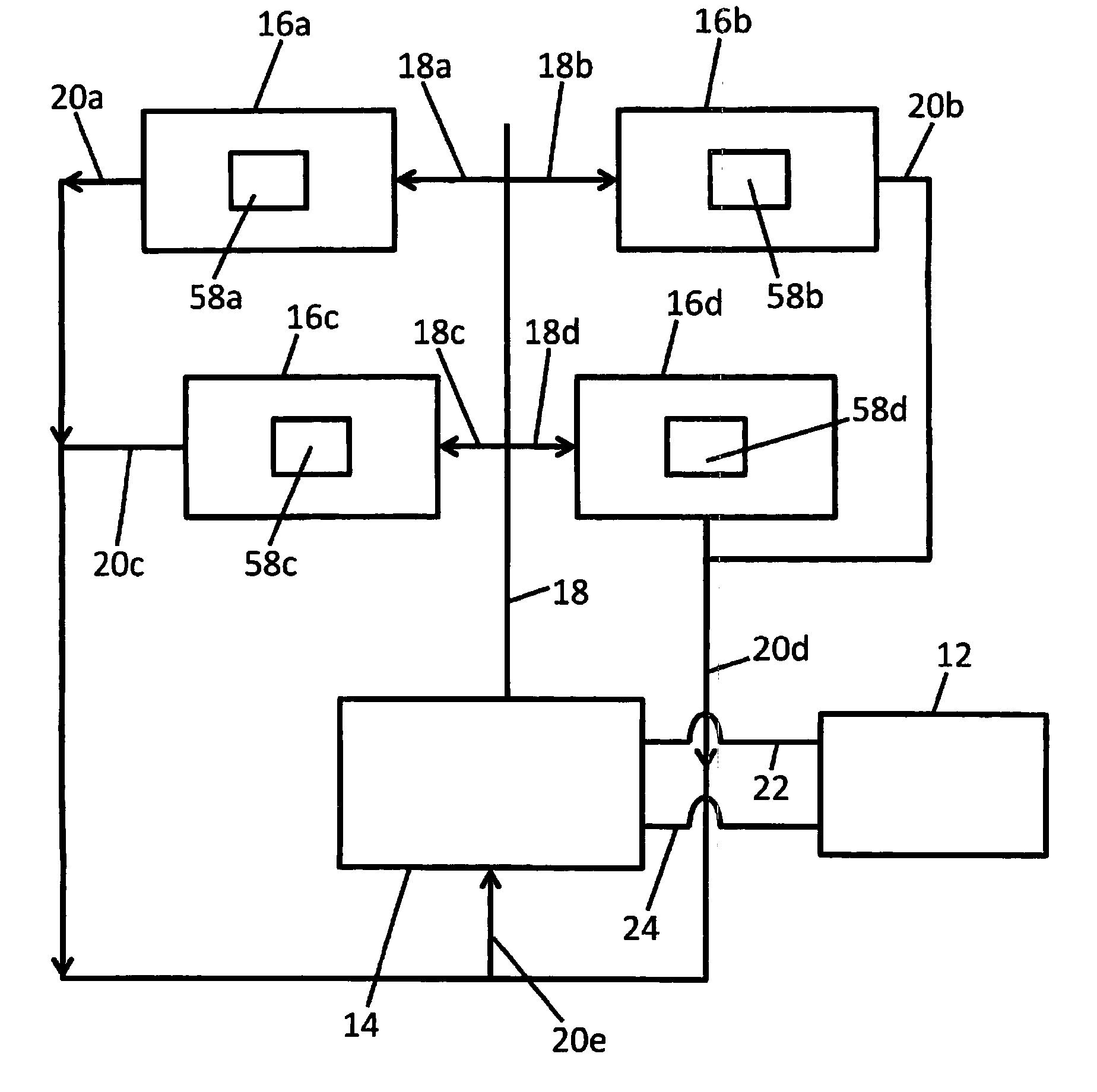
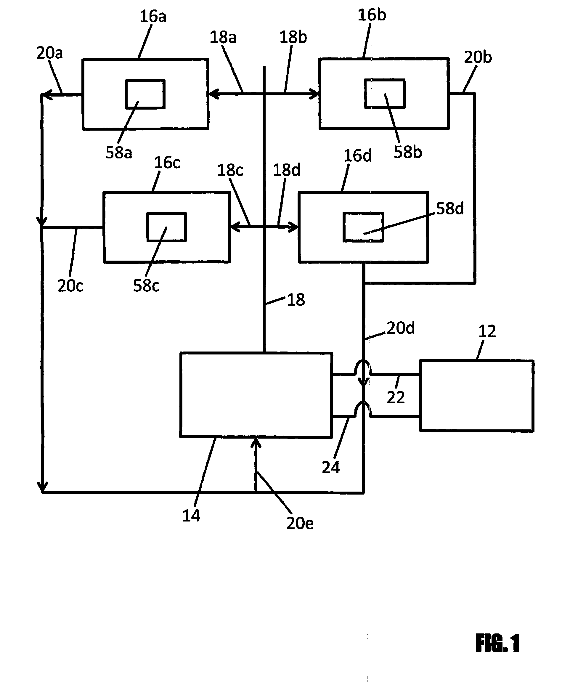
[0004]According to an embodiment of the present invention, there is disclosed high-efficiency HVAC system for use in a house or building, having a plurality of components. The components include flexible, plastic duct tubing forming supply pipes that connect an air handler and a plurality of zones to deliver supply air to the zones in the house or building and return pipes that connect the air handler and the plurality of zones to re-circulate return air from the zones to the air handler; the air handler having a fan assembly powered by a variable blower motor to blow supply air through the supply pipes to the plurality of zones to individually control air humidity, air purity and air temperature within the zones in the building or house; a heat pump having a variable compressor powered by a variable compressor motor to direct a working fluid to and from the air handler and a variable fan motor that rotates a fan blade within the heat pump; and a circuit control system for adjusting the variable compressor motor and the variable fan motor in the heat pump and the variable blower motor in the air handler in response to the capacity required by the HVAC system.
[0005]According to another embodiment of the present invention, a method of operating a high-efficiency HVAC system for use in house or building, having a plurality of components is disclosed. The method includes delivering supply air to a plurality of zones in the house or building from an air handler through flexible, plastic duct tubing; re-circulating return air from the zones to the air handler through flexible, plastic duct tubing; blowing supply air with a fan assembly powered by a variable blower motor disposed within the air handler to the plurality of zones; directing a working fluid from a heat pump having a variable compressor powered by a variable compressor motor to and from the air handler; rotating a fan blade within the heat pump with a variable fan; and adjusting the variable compressor motor and the variable fan motor in the heat pump and the variable blower motor in the air handler in response to the capacity required by the HVAC system.
[0006]According to another embodiment of the present invention, a high-efficiency HVAC system kit for use in house or building, having a plurality of components is disclosed. The components include flexible, plastic duct tubing forming supply pipes that connect an air handler and a plurality of zones to deliver supply air to the zones in the house or building and return pipes that connect the air handler and the plurality of zones to re-circulate return air from the zones to the air handler; the air handler having a fan assembly powered by a variable blower motor to blow supply air through the supply pipes to the plurality of zones to individually control air humidity, air purity and air temperature within the zones in the building or house; a heat pump having a variable compressor powered by a variable compressor motor to direct a working fluid to and from the air handler and a variable fan motor that rotates a fan blade within the heat pump; and a circuit control system for adjusting the variable compressor motor and the variable fan motor in the heat pump and the variable blower motor in the air handler in response to the capacity required by the HVAC system.

Problems solved by technology

The HVAC industry is economically sensitive to costs.
Of a more global interest though, is the cost to operate and maintain HVAC systems.

Method used


Image

  • Heating, ventilation, and air conditioning system
  • Heating, ventilation, and air conditioning system
  • Heating, ventilation, and air conditioning system

Examples


Embodiment Construction

[0016]In the description that follows, numerous details are set forth in order to provide a thorough understanding of the present invention. It will be appreciated by those skilled in the art that variations of these specific details are possible while still achieving the results of the present invention. Well-known processing steps are generally not described in detail in order to avoid unnecessarily obfuscating the description of the present invention.

[0017]In the description that follows, exemplary dimensions may be presented for an illustrative embodiment of the invention. The dimensions should not be interpreted as limiting. They are included to provide a sense of proportion. Generally speaking, it is the relationship between various elements, where they are located, their contrasting compositions, and sometimes their relative sizes that is of significance.

[0018]In the drawings accompanying the description that follows, often both reference numerals and legends (labels, text de...


PUM


Abstract

A high-efficiency HVAC system and method of operation, for use in a house or building, having a plurality of components, including flexible, plastic duct tubing forming supply pipes that connect an air handler and a plurality of zones to deliver supply air to the zones and return pipes that connect the air handler and the zones to re-circulate return air; the air handler having a fan assembly powered by a variable blower motor to blow supply air to the zones; a heat pump having a variable compressor powered by a variable compressor motor to direct a working fluid to and from the air handler and a variable fan motor that rotates a fan blade within the heat pump; and a circuit control system for adjusting the variable compressor motor and the variable fan motor in the heat pump and the variable blower motor in the air handler.

Description

TECHNICAL FIELD OF THE INVENTION[0001]The present invention relates generally to a high-efficiency HVAC system for use in a house or building. More specifically, the present invention relates to a HVAC system including flexible, plastic duct tubing forming supply pipes and return pipes that connect an air handler and a plurality of zones, the air handler having a fan assembly powered by a variable blower motor, a heat pump having a variable compressor powered by a variable compressor motor and a variable fan motor, and a circuit control system for adjusting the variable compressor motor, the variable fan motor and the variable blower motor.BACKGROUND OF THE INVENTION[0002]Heating, ventilation and air-conditioning (HVAC) systems have to satisfy three primary comfort functions, namely heating and cooling, humidity control, and ventilation. These functions are usually delegated to either a central forced convection air-conditioning system, or unitary air-conditioners, or hydraulic heat...

Claims


Application Information

Patent Timeline
Patent Type & Authority Applications(United States)
IPC IPC(8): F25D17/08
CPCF25D17/08F24F3/044F24F2203/02F25B13/00F25B27/00F25B49/02F25B2313/0293F25B2600/0253F24F11/83Y02B30/70F24F11/85F24F11/84
Inventor SCHLESINGER, STEPHEN
Owner SCHLESINGER STEPHEN
Why Eureka
Try Eureka