Eureka AIR delivers breakthrough ideas for toughest innovation challenges, trusted by R&D personnel around the world.

Package substrate, method of manufacturing the package substrate and semiconductor package including the package substrate

Inactive Publication Date: 2014-09-04
HALDEX BRAKE PROD AB +1
View PDF4 Cites 0 Cited by
  • Summary
  • Abstract
  • Description
  • Claims
  • Application Information

AI Technical Summary

Benefits of technology

The patent text describes a package substrate and a method of manufacturing it that allows for the easy connection of plating lines to rows of land arrays with a narrow pitch. The package substrate includes an insulating substrate, a first land array, a second land array, a first plating line, and a second plating line. The first plating line is connected to the outer lands of the second land array, while the second plating line is connected between the outer and inner lands of the second land array. The second plating line has a narrower width than the first plating line and can be easily removed. The package substrate can be used in a semiconductor package to connect with external terminals or other components. The technical effect of this invention is to provide a package substrate that allows for efficient and reliable connection of plating lines to land arrays with a narrow pitch.

Problems solved by technology

However, because the package substrate may have a limited size, the land arrays having the narrow pitch may be arranged in at least three rows.
In contrast, the plating line may not be easily connected to a central land array that is positioned on a central portion of the package substrate due to the narrow pitch of the land arrays.

Method used


Image

  • Package substrate, method of manufacturing the package substrate and semiconductor package including the package substrate
  • Package substrate, method of manufacturing the package substrate and semiconductor package including the package substrate
  • Package substrate, method of manufacturing the package substrate and semiconductor package including the package substrate

Examples


Embodiment Construction

[0039]Various example embodiments will be described more fully hereinafter with reference to the accompanying drawings, in which some example embodiments are shown. The disclosed subject matter may, however, be embodied in many different forms and should not be construed as limited to the example embodiments set forth herein. Rather, these example embodiments are provided so that this disclosure will be thorough and complete, and will fully convey the scope of the disclosed subject matter to those skilled in the art. In the drawings, the sizes and relative sizes of layers and regions may be exaggerated for clarity.

[0040]It will be understood that when an element or layer is referred to as being “on,”“connected to” or “coupled to” another element or layer, it can be directly on, connected or coupled to the other element or layer or intervening elements or layers may be present. In contrast, when an element is referred to as being “directly on,”“directly connected to” or “directly cou...


PUM

PropertyMeasurementUnit
Currentaaaaaaaaaa
Electrical conductoraaaaaaaaaa
Widthaaaaaaaaaa

Abstract

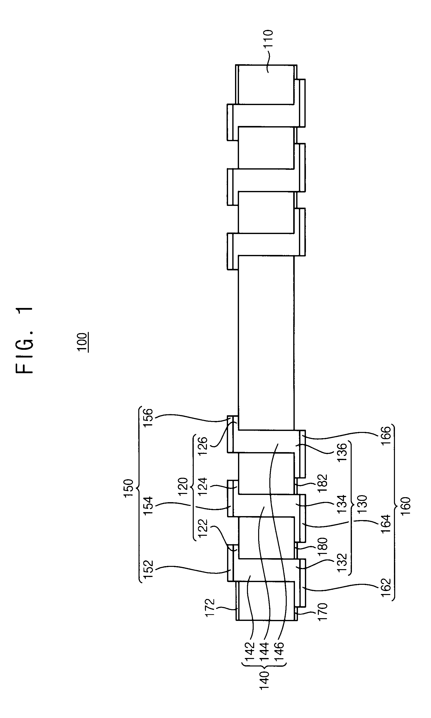
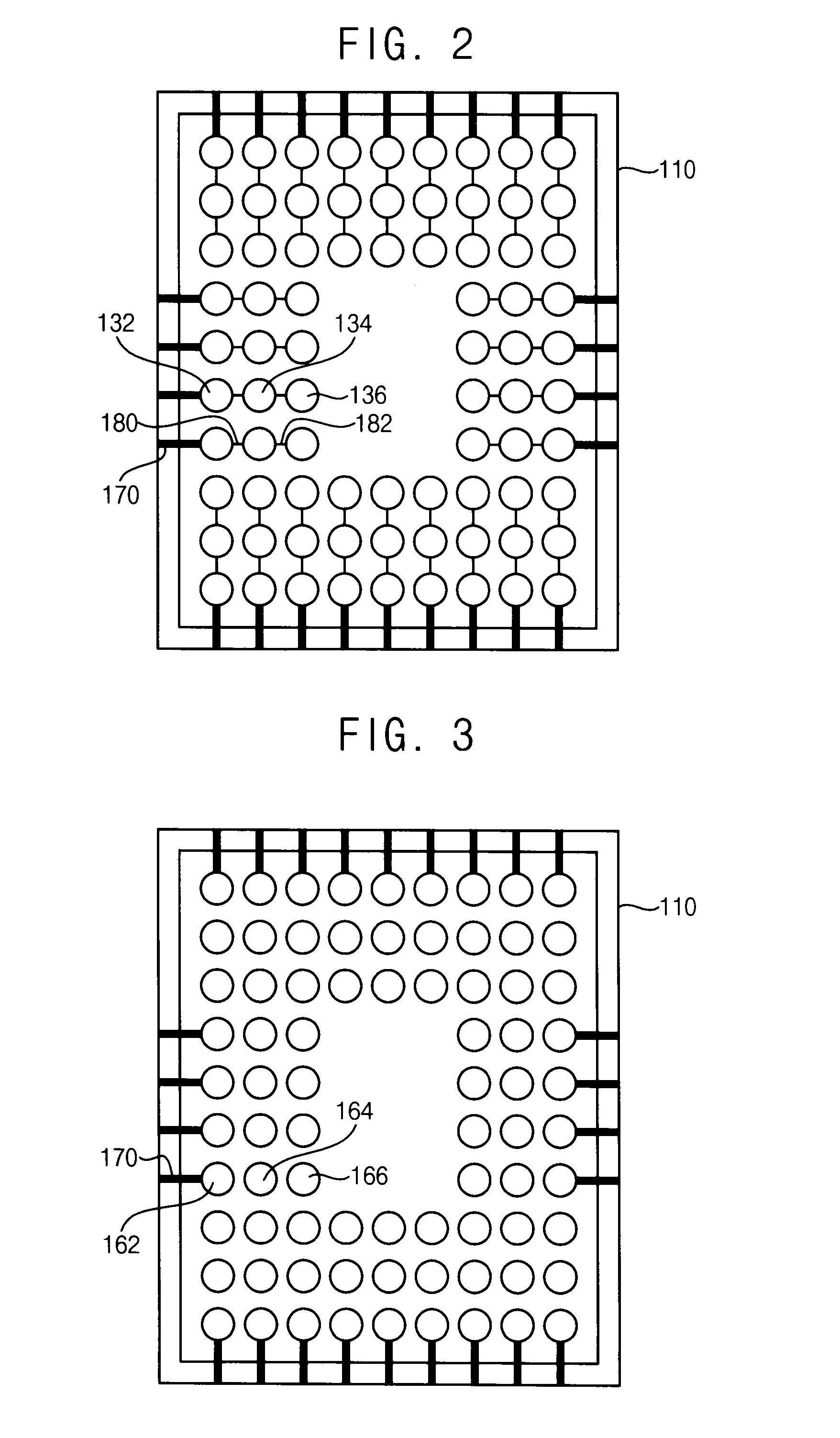
A package substrate may include an insulating substrate, a first land array, a second land array, a first plating line and a second plating line. The first land array may be arranged on a first surface of the insulating substrate. The second land array may be arranged on a second surface of the insulating substrate opposite to the first surface. The second land array may be electrically connected to the first land array. The second land array may include outer lands and inner lands. The first plating line may be connected to the outer lands. The second plating line may be connected between the outer lands and the inner lands. The second plating line may have a width narrower than that of the first plating line. The second plating line may be removed by applying a removing current to the first plating line prior to the first plating line.

Description

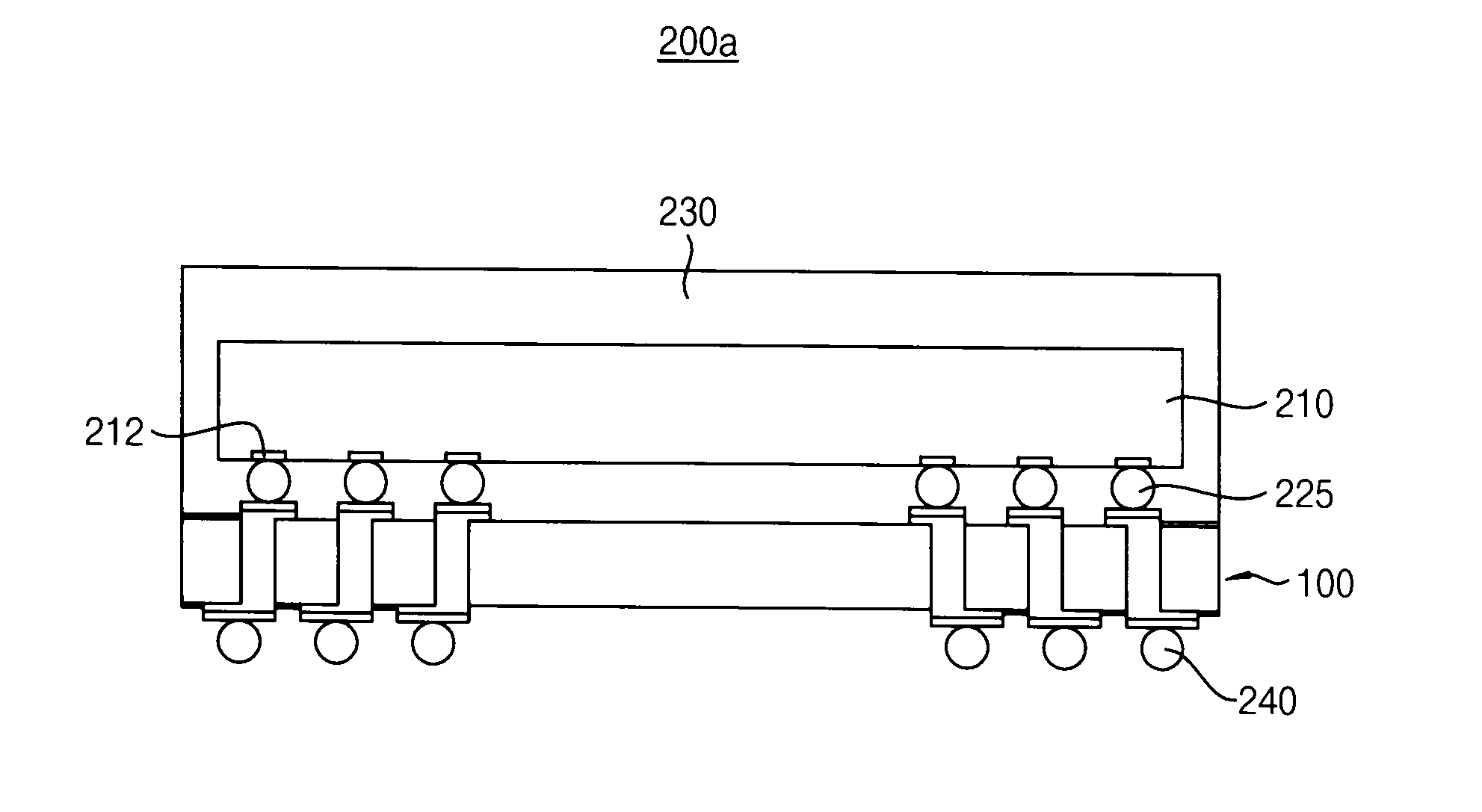
CROSS-RELATED APPLICATION[0001]This application claims priority under 35 USC §119 to Korean Patent Application No. 10-2013-0022668, filed on Mar. 4, 2013 in the Korean Intellectual Property Office (KIPO), the contents of which are herein incorporated by reference in their entirety.BACKGROUND[0002]1. Field[0003]Example embodiments relate to a package substrate, a method of manufacturing the package substrate and a semiconductor package including the package substrate. More particularly, example embodiments relate to a package substrate having a land array, a method of manufacturing the package substrate and a semiconductor package including the package substrate.[0004]2. Description of the Related Art[0005]Generally, various semiconductor fabrication processes may include using a semiconductor substrate to form a plurality of semiconductor chips. In order to mount the semiconductor chips on a printed circuit board (PCB), a packaging process may be performed using the semiconductor ch...

Claims


Application Information

Patent Timeline
IPC IPC(8): H05K1/11H01L23/498H05K3/24
CPCH05K1/116H05K3/242H01L23/49811H01L23/3128H01L23/49827H01L23/49866H01L23/5381H01L24/16H01L24/32H01L24/48H01L24/73H01L25/0657H01L2224/16145H01L2224/16225H01L2224/16235H01L2224/32145H01L2224/48091H01L2224/48227H01L2224/48235H01L2224/73265H01L2225/0651H01L2225/06513H01L2225/06517H01L2225/06541H01L2225/06562H01L2924/00014H01L2924/15311H01L2924/181H05K1/113H05K2201/09227H05K2201/10734H05K2203/175Y10T29/49155Y10T29/49165H01L2224/32225H01L2924/00012H01L2224/45099H01L2224/45015H01L2924/207H01L23/48H01L23/481
Inventor YOON, TAE-YOUNG
Owner HALDEX BRAKE PROD AB
Why Eureka
Eureka Blog
Learn More