Ion exchanger and cooler having ion exchanger

a technology of ion exchanger and cooler, which is applied in the field of ion exchanger, can solve the problems of difficult to improve both the ion exchange rate and the pressure loss, and achieve the effects of reducing the cross-sectional area of the flow path, improving both the ion exchange rate and the pressure loss, and easy increase of pressure loss in the bypass path

Active Publication Date: 2014-09-04
NISSAN MOTOR CO LTD +1
View PDF6 Cites 6 Cited by
  • Summary
  • Abstract
  • Description
  • Claims
  • Application Information

AI Technical Summary

Benefits of technology

[0008]It is therefore an object of the present invention to provide an ion exchanger capable of suppressing an increase of the pressure loss and improving the ion exchange rate.

Problems solved by technology

Therefore, a pressure loss in the bypass path easily increases.
In addition, it is difficult to improve both the ion exchange rate and the pressure loss.

Method used


Image

  • Ion exchanger and cooler having ion exchanger
  • Ion exchanger and cooler having ion exchanger
  • Ion exchanger and cooler having ion exchanger

Examples


first embodiment

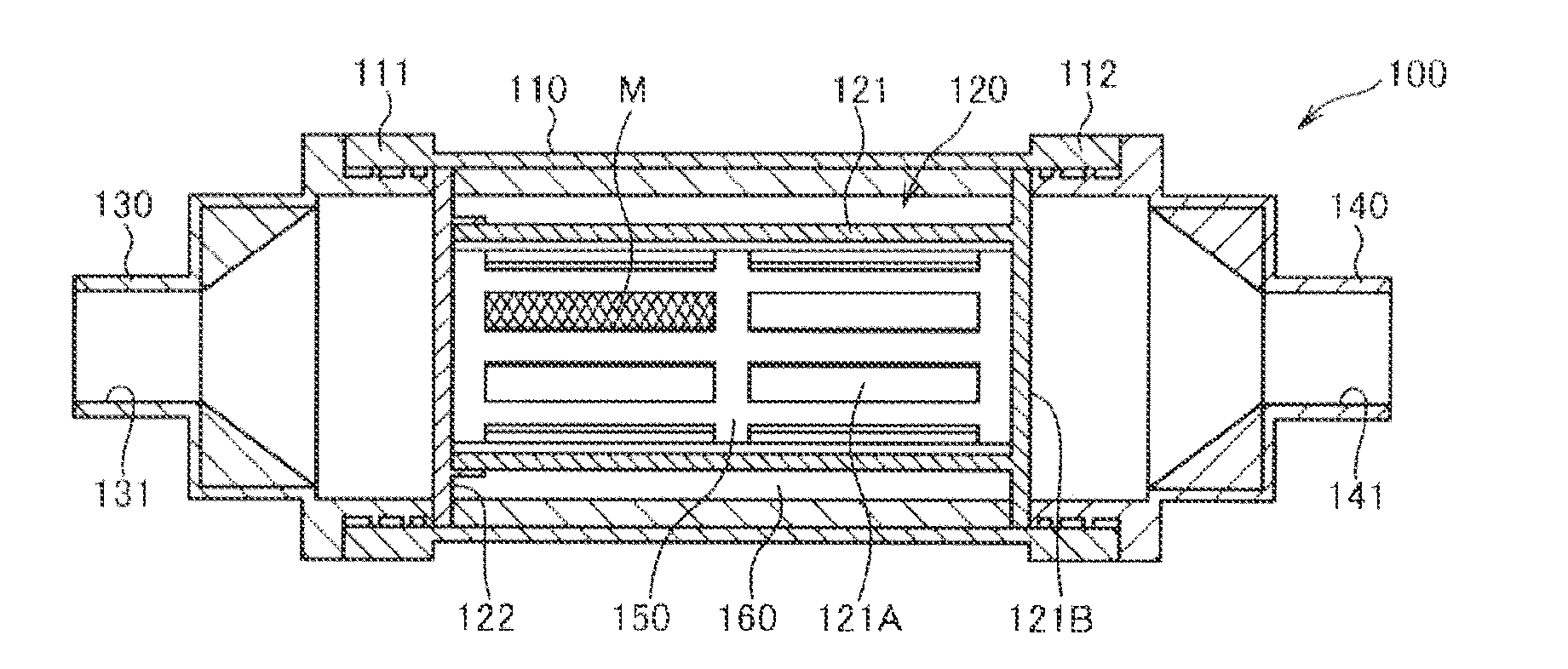
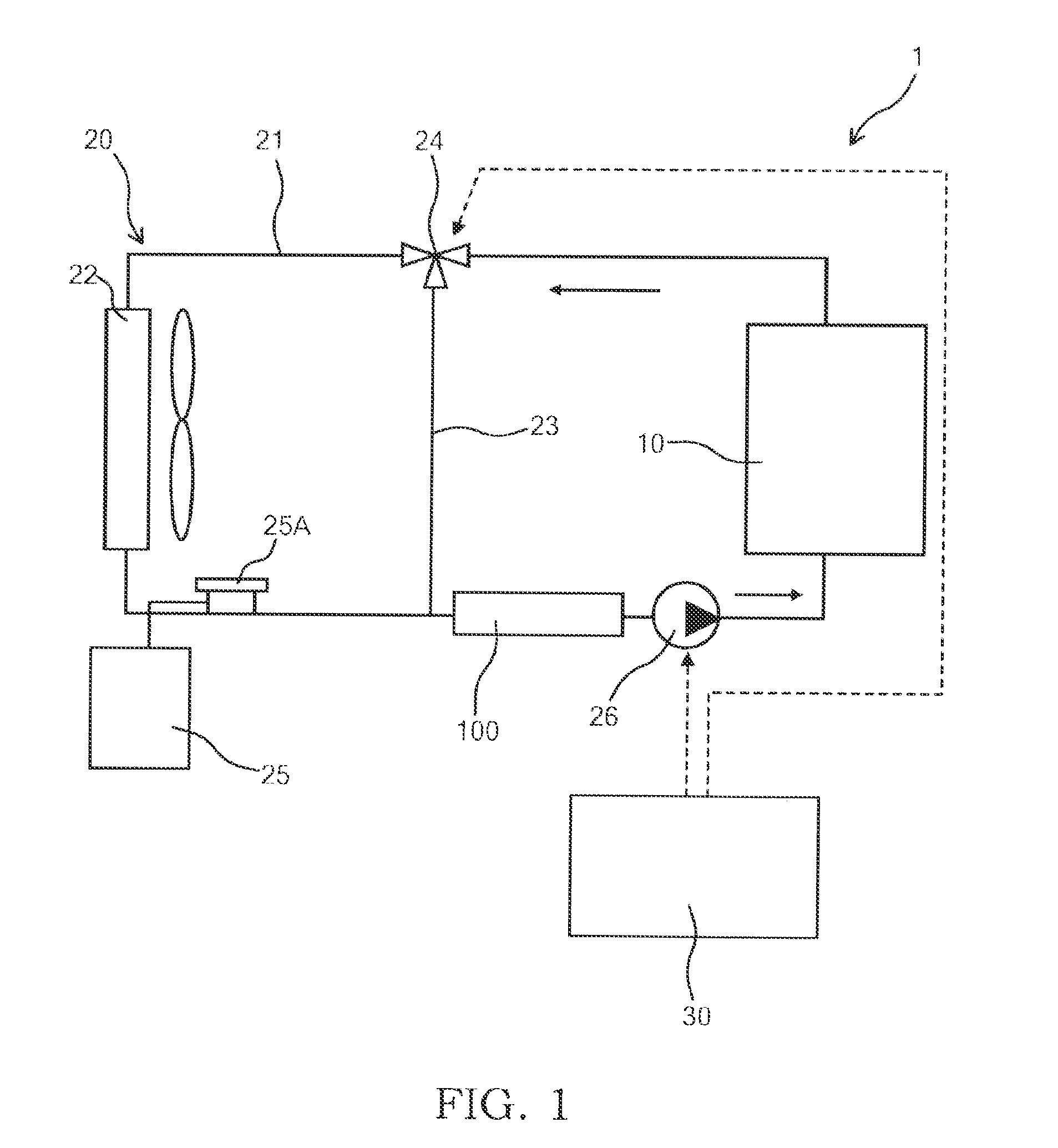
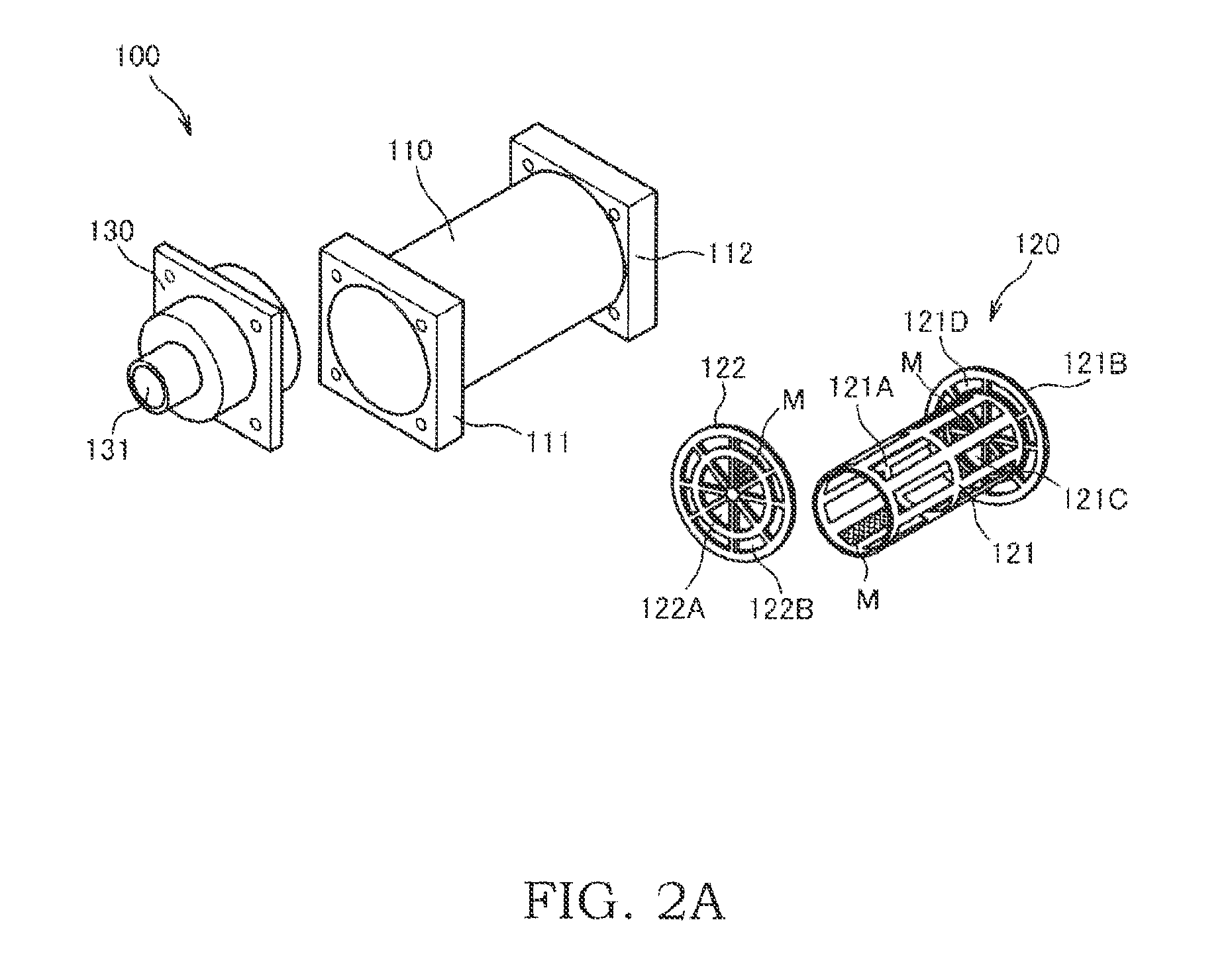
[0027]FIG. 1 is a schematic view illustrating a fuel cell system 1 having an ion exchanger 100 according to a first embodiment of the present invention.

[0028]As illustrated in FIG. 1, the fuel cell system 1 includes a fuel cell stack 10, a cooler 20 that cools the fuel cell stack 10, and a controller 30 that executes a system control.

[0029]The fuel cell stack 10 is configured by stacking a predetermined number of fuel cells. The fuel cell stack 10 generates electric power using an anode gas supplied from an anode gas supply unit and a cathode gas supplied from a cathode gas supply unit. The electric power generated by the fuel cell stack 10 is supplied to various electric devices such as a driving motor for driving a vehicle.

[0030]The cooler 20 is a device for cooling the fuel cell stack 10 using a coolant. As the coolant, pure water or a glycol-based antifreeze fluid may be employed. The cooler 20 includes a coolant circulation path 21, a radiator 22, a bypass path 23, a three-way ...

second embodiment

[0062]An ion exchanger 100 according to a second embodiment of the invention will be described with reference to FIGS. 6 and 7. The second embodiment is different from the first embodiment in the configuration of the through-hole 121A of the cylindrical portion 121 of the inner casing 120. It is noted that, in the following embodiments, like reference numerals denote like elements as in the first embodiment, and the description thereof will not be repeated.

[0063]FIG. 6 is a longitudinal cross-sectional view illustrating the ion exchanger 100 according to the second embodiment. FIG. 7 is a diagram illustrating a relationship between an ion exchange rate and a flow volume of the coolant passing through the ion exchanger. In FIG. 7, the solid line denotes data of the ion exchanger 100 according to the first embodiment, and the dotted line denotes data of the ion exchanger 100 according to the second embodiment.

[0064]As illustrated in FIG. 6, in the ion exchanger 100 according to the se...

third embodiment

[0068]An ion exchanger 100 according to a third embodiment of the invention will be described with reference to FIG. 8. The third embodiment is different from the first and second embodiment in a configuration of the mesh M provided in the through-hole 121A of the inner casing 120 and the like.

[0069]FIG. 8 is a diagram schematically illustrating a longitudinal cross section of the ion exchanger 100 according to the third embodiment.

[0070]As illustrated in FIG. 8, in the ion exchanger 100, meshes M1 as first meshes are provided in the through dudes 121A of the cylindrical portion 121 and the communicating portions 121C of the downstream end 121B, and meshes M2 as second meshes are provided in the communicating portions 122A and 122B of the lid portion 122.

[0071]The mesh M1 provided in the through-hole 121A and the communicating portion 121C has a screen opening smaller than a particle size of the ion exchange resin. The screen opening of the mesh M1 is set to, approximately, 200 micr...


PUM

PropertyMeasurementUnit
particle sizeaaaaaaaaaa
electric poweraaaaaaaaaa
electrochemical reactionaaaaaaaaaa

Abstract

An ion exchanger configured to remove an impurity ion of a coolant for cooling a fuel cell, the ion exchanger includes an inflow portion having an inflow path where the coolant enters, a discharge portion having a discharge path for discharging the coolant, an outer casing having an upstream end where the inflow portion is provided and a downstream end where the discharge portion is provided, an inner casing housed inside the outer casing, an outer path formed between the inner casing and the outer casing to cause the inflow path and the discharge path to communicate with each other, and an inner path that is formed inside the inner casing to cause the inflow path and the discharge path to communicate with each other and is configured to enclose an ion exchange resin capable of removing an impurity ion of the coolant. The inner casing has a through-hole that causes the inner path end the outer path to communicate with each other.

Description

TECHNICAL FIELD[0001]The present invention relates to an ion exchanger for removing an impurity ion from a fluid and a cooler having the ion exchanger.BACKGROUND ART[0002]A fuel cell includes an anode, a cathode, and an electrolytic membrane interposed therebetween. The fuel cell generates electric power using an anode gas containing hydrogen supplied to the anode and a cathode gas containing oxygen supplied to the cathode. An electrochemical reaction generated in both the anode and the cathode can be expressed as follows.Anode: 2H2→4H+30 4e−  (1)Cathode: 4H++4e−+O2→2H2O  (2)[0003]Through the electrochemical reaction of Expressions (1) and (2), the fuel cell generates an electromotive force of, approximately, 1 V.[0004]When the fuel cell is employed as a power source of a vehicle, a fuel cell stack obtained by stacking several hundreds of fuel cells is used. In addition, a fuel cell system capable of supplying an anode gas and a cathode gas to the fuel cell stack is provided to outp...

Claims


Application Information

Patent Timeline
Patent Type & Authority Applications(United States)
IPC IPC(8): H01M8/04C02F1/42
CPCC02F1/42H01M8/04701B01J47/022B01J47/026C02F1/006C02F2103/023C02F2301/028H01M8/04029H01M8/04044H01M2008/1095Y02E60/50C02F2301/024C02F2301/026
Inventor TAKEMOTO, SHINICHIROSHIRAYANAGI, SATOSHI
Owner NISSAN MOTOR CO LTD
Why Eureka
Try Eureka