Imaging apparatus and rigid endoscope

a rigid endoscope and imaging apparatus technology, applied in the field of imaging apparatus, can solve the problems of reducing the size of the imaging apparatus as a whole, affecting the work affecting the work efficiency of the imaging apparatus, so as to achieve the effect of advantageously reducing the size of the imaging section that is inserted into a narrow observation area

Inactive Publication Date: 2014-09-04
SERENDIPITY
View PDF15 Cites 19 Cited by
  • Summary
  • Abstract
  • Description
  • Claims
  • Application Information

AI Technical Summary

Benefits of technology

[0014]Specifically, the drive section is provided at a position far from the spherical housing through the drive wire to enable free movement of the spherical housing without the necessity of directly mounting a drive section having an imaging means to the spherical housing. The spherical housing only has to be supported by a base that enables the spherical housing to freely move along the surface thereof.
[0015]In the imaging apparatu

Problems solved by technology

However, in Patent Documents 1 and 2, there is a problem that size reduction of the apparatus as a whole is constrained by the size of the drive mechanism, such as the stators, because the stators or the stacked piezoelectric actuator are directly mounted to the spherical actuator or the spherical housing inserted into a narrow space.
Further, when s

Method used


Image

  • Imaging apparatus and rigid endoscope
  • Imaging apparatus and rigid endoscope
  • Imaging apparatus and rigid endoscope

Examples


Embodiment Construction

[0026]With reference to the drawings, hereinafter are described some embodiments of the present disclosure. However, the present disclosure shall not be limited to the embodiments described below. The components identical with or similar to each other between the drawings indicate that the components have the same configuration and thus the components are given the same reference numerals for the sake of omitting unnecessary explanation.

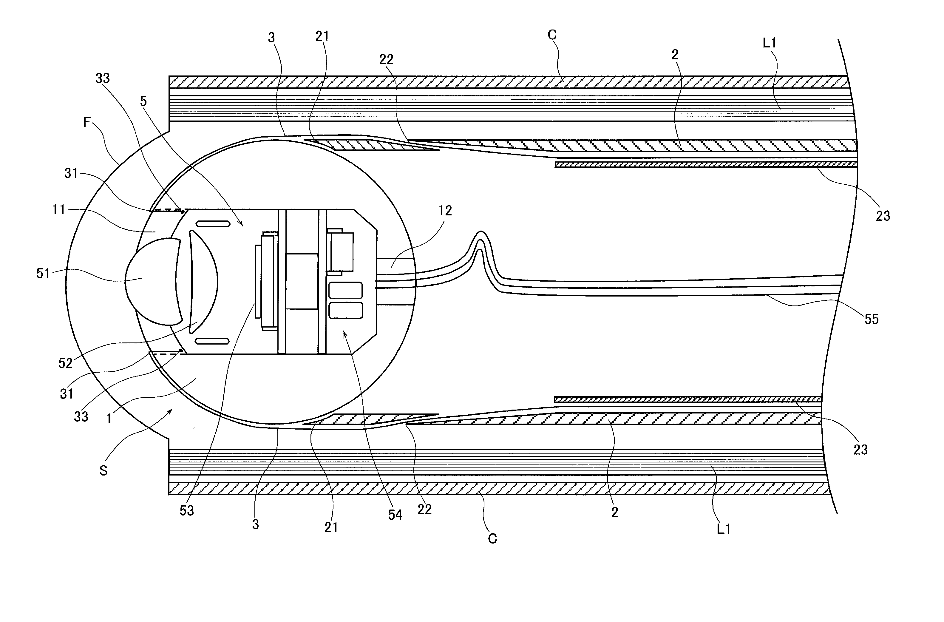
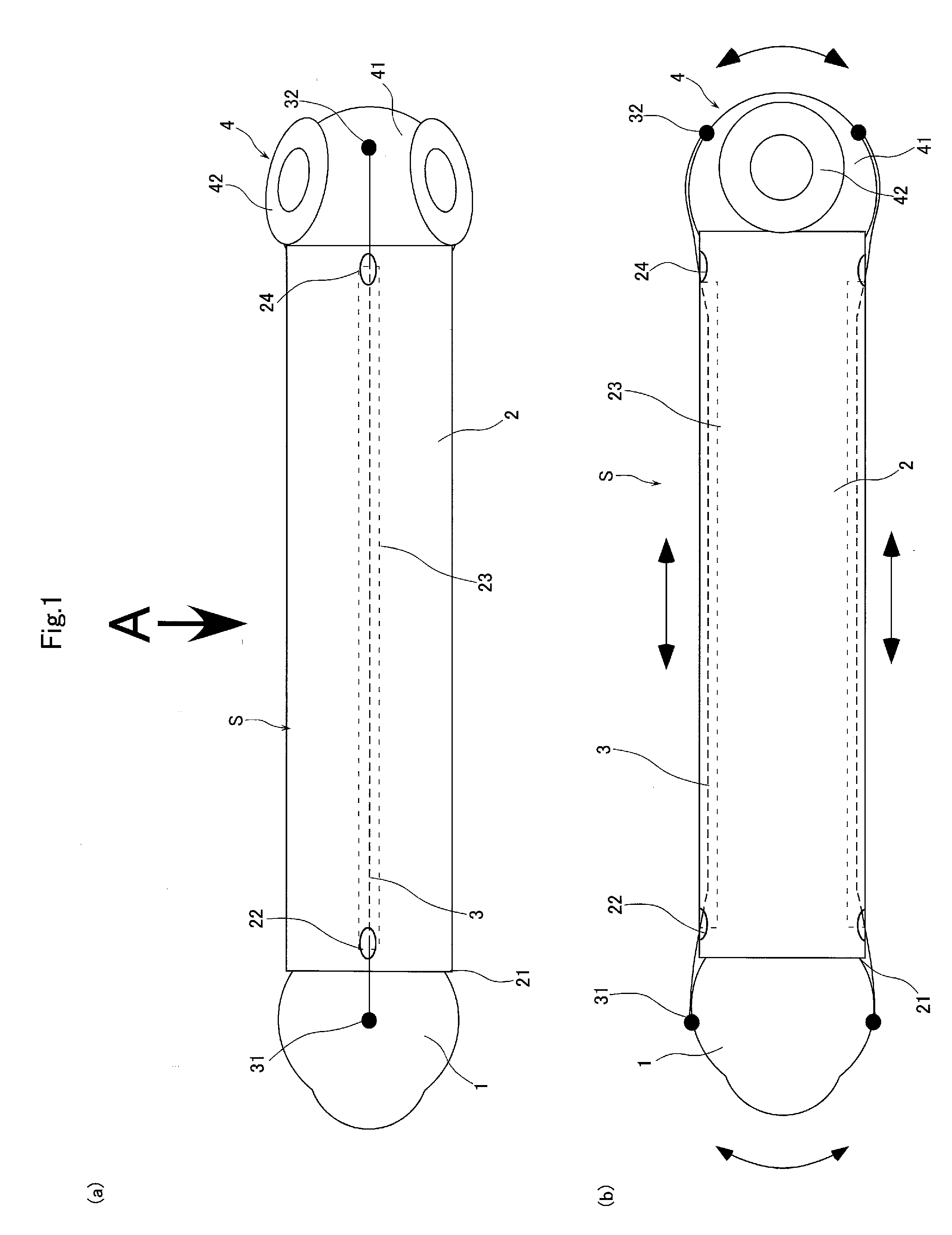
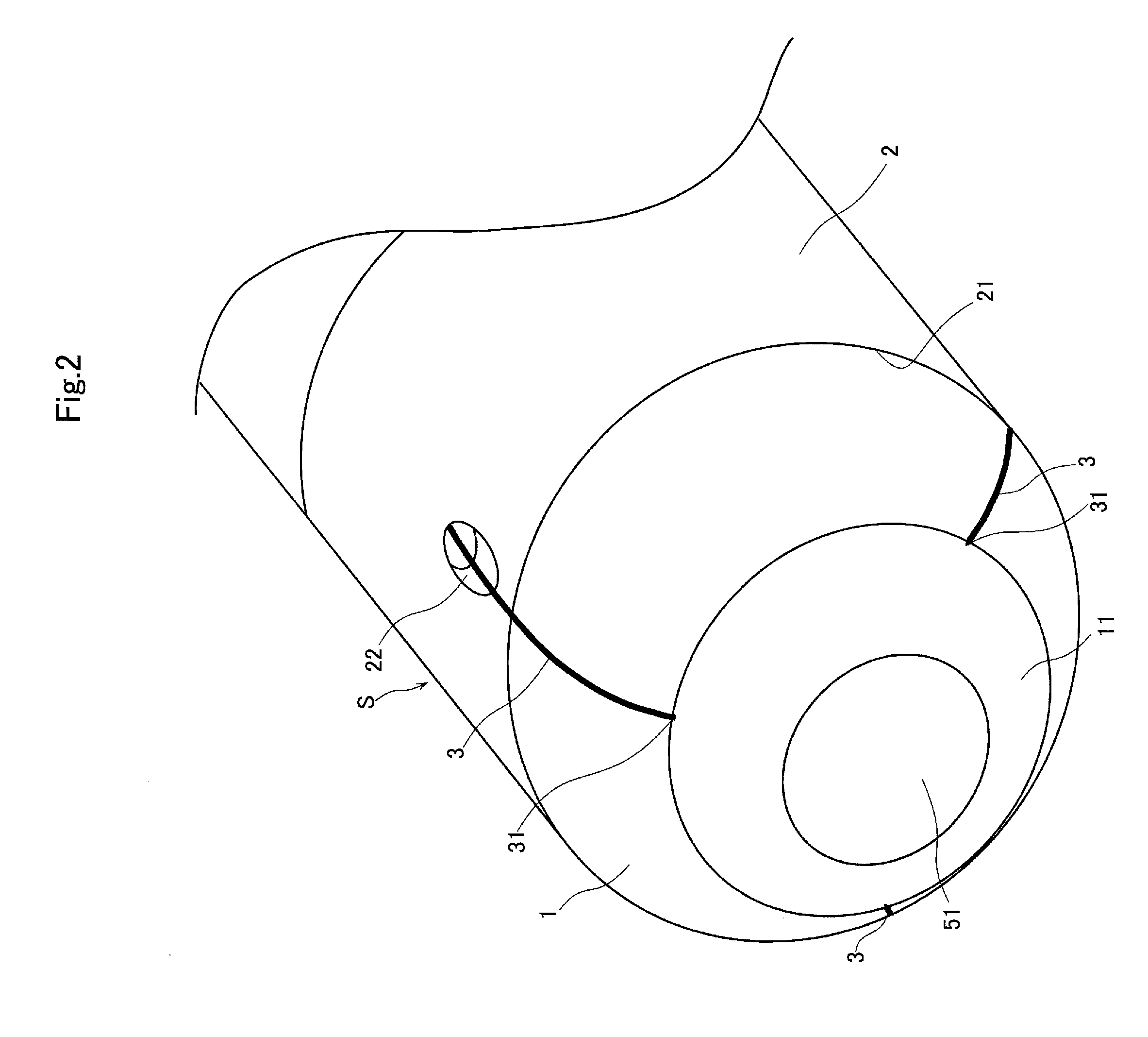
[0027]Referring to FIGS. 1 and 2, a reference numeral 1 indicates a spherical housing that holds therein an image-wise light receiving unit 5 that configures an imaging apparatus S related to the present embodiment. The image-wise light receiving unit 5 is based on a concept of including a solid-state image sensing device, such as a CCD (charge-coupled device) or a CMOS (complementary metal-oxide semiconductor), and an optical device that receives image-wise light and transmits the light to the solid-state image sensing device, as in a light-receivin...


PUM


Abstract

An aim is to provide an imaging apparatus that can reduce the size without being constrained by the size of a mechanism that drives the apparatus, and can accurately move a field of view over a wide range in a narrow space. The apparatus includes an image-wise light receiving means, a spherical housing that holds therein the image-wise light receiving means, a base that supports the spherical housing and enables the spherical housing to freely move along a surface thereof, a drive wire having an end fixed to the spherical housing, and a drive section to which the other end of the drive wire is fixed to drive the free movement of the spherical housing via the drive wire.

Description

BACKGROUND[0001]1. Field of the Disclosure[0002]The present disclosure relates to an imaging apparatus and, more particularly, to an imaging apparatus that is small in size and able to expand the range of rotational movement in a field of view.[0003]2. Discussion of the Background Art[0004]A conventional imaging apparatus used in a narrow space in performing an endoscopic examination, piping inspection, or the like is engineered to reduce the size of the imaging section and to ensure any direction in a field of view. For example, a CCD camera and a lens are housed in a spherical actuator, and the rotor that forms the spherical actuator is held by a plurality of stators. The stators are permitted to generate torque around their respective axes to realize the movement of the CCD camera based on three degrees of freedom (e.g., see Patent Document 1).[0005]For example, a known imaging apparatus has a spherical housing that houses an imaging means therein, while the housing is mounted wi...

Claims


Application Information

Patent Timeline
IPC IPC(8): A61B1/045A61B1/06
CPCA61B1/06A61B1/045A61B1/051A61B1/00183A61B1/0627A61B1/0655
Inventor HANABUSA, SHINICHI
Owner SERENDIPITY
Why Eureka
Try Eureka