Cast-in anchor system

a technology of cast-in anchors and concrete, which is applied in the direction of threaded fasteners, screws, rod connections, etc., can solve the problems of weakened by galvanic corrosion, and aluminum′ being generally disfavored as a material for reinforced concrete. to achieve the effect of preventing galvanic corrosion

Inactive Publication Date: 2014-09-11
RICHARDSON DOUGLAS S
View PDF12 Cites 39 Cited by
  • Summary
  • Abstract
  • Description
  • Claims
  • Application Information

AI Technical Summary

Benefits of technology

[0018]The preferred bolt retainer is also extruded, cut to length and undergoes further manufacturing processes to prevent galvanic corrosion. When the processes are complete, an industry standard bolt can be inserted into a bolt-hole in the bolt retainer. Leading with its threaded portion, the bolt is inserted into the bolt-hole until the head of the bolt (hereinafter “bolt-head”) contacts a bearing surface on the bolt retainer. Once fully inserted, one or more side surfaces of the bolt-head are adjacent one or more bolt-lock tabs extending from the bolt retainer. The bolt-lock tabs prevent the bolt from rotating about its vertical axis when a nut is threaded onto it and the connection is tightened. Together, the bolt retainer and the bolt form the bolt-retainer assembly.
[0019]The bolt-retainer assembly is placed into the anchor-channel interior, preferably through an entry point in the retaining lips of the cast-in anchor. Once in the anchor-channel interior, the bolt-retainer assembly is longitudinally displaceable along the length of the anchor channel while the threaded portion of the bolt remains at least partially out of the anchor-channel interior, extending through an opening between the retaining lips. As detailed herein below, the preferred bolt retainer allows a user to remove his / her hand from the bolt-retainer assembly and no initial tension is required to hold the bolt-retainer assembly in its desired location in the anchor channel prior to tightening the connection.
[0020]With the bolt-retainer assembly in place, an object is placed over the threaded portion of the bolt. A washer and nut are placed on the bolt and the nut is tightened to secure the connection. As the nut is tightened, the bolt-head exerts force on the bearing surface of the bolt retainer and pulls the bolt retainer toward the opening of the anchor-channel interior. The bolt retainer, however, has one or more locking surfaces which engage against the retaining lips of the anchor channel, thereby preventing the bolt retainer from exiting the anchor-channel interior. With the bolt retainer prevented from exiting the anchor-channel interior the connection may be tightened and the object is anchored to the concrete structure.

Problems solved by technology

Aluminum′ however, is generally disfavored as a material for use in reinforced concrete because aluminum which comes into electrical contact with reinforcing steel has been shown to undergo galvanic corrosion due to the different electrode potentials of the dissimilar metals.
Studies have shown that such galvanic corrosion weakens both the structure of the aluminum and the surrounding concrete.

Method used


Image

  • Cast-in anchor system
  • Cast-in anchor system
  • Cast-in anchor system

Examples


Embodiment Construction

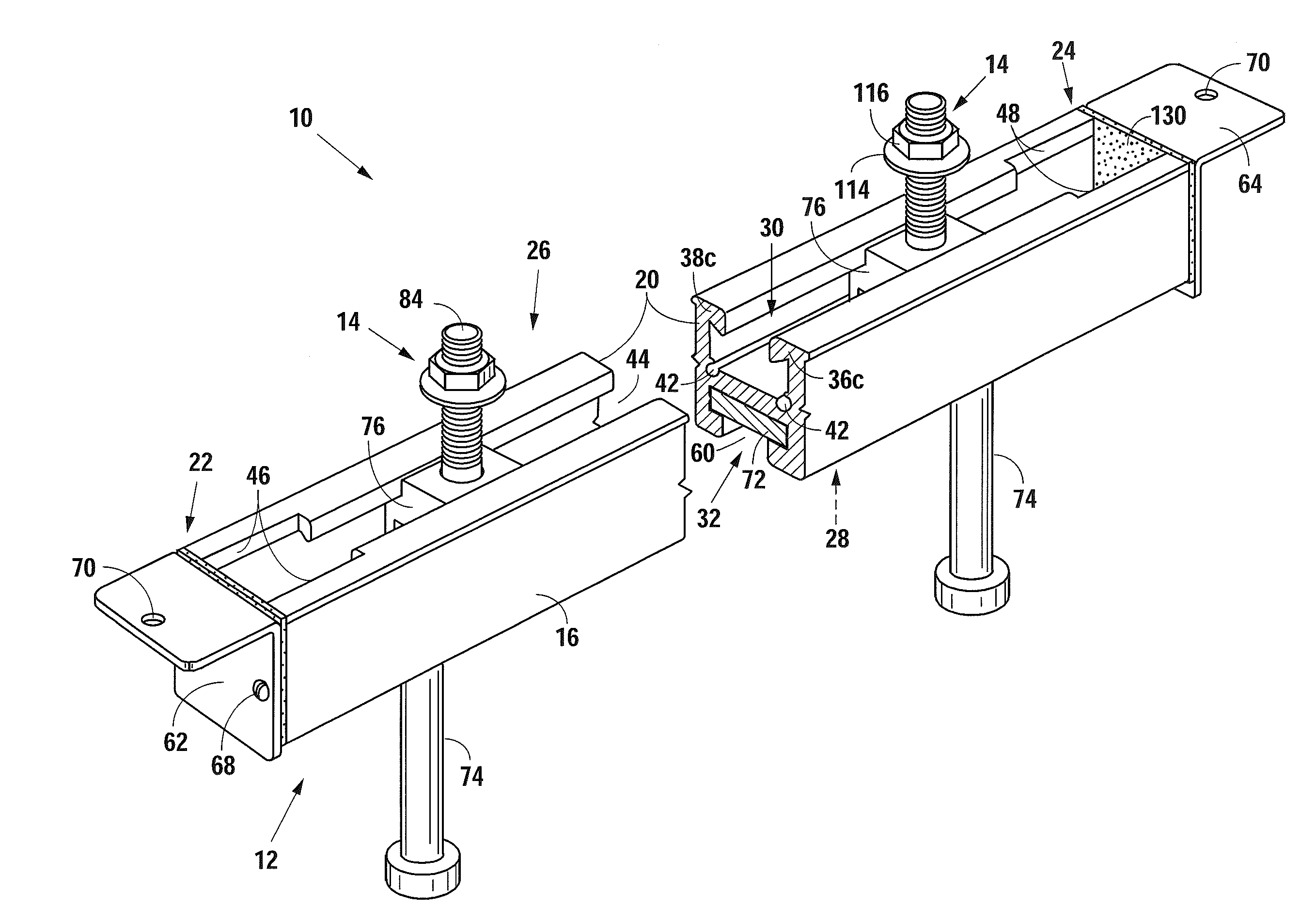
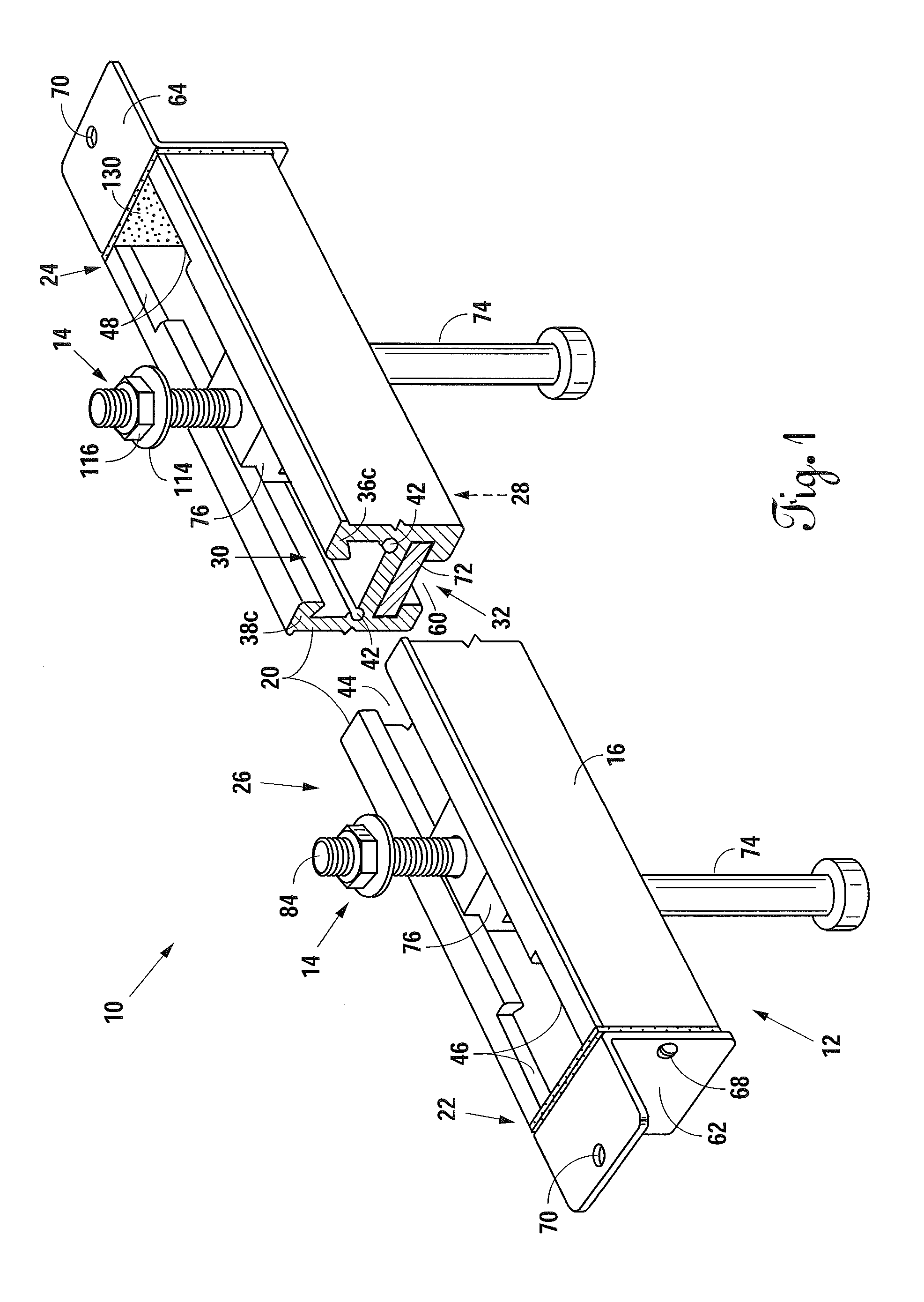
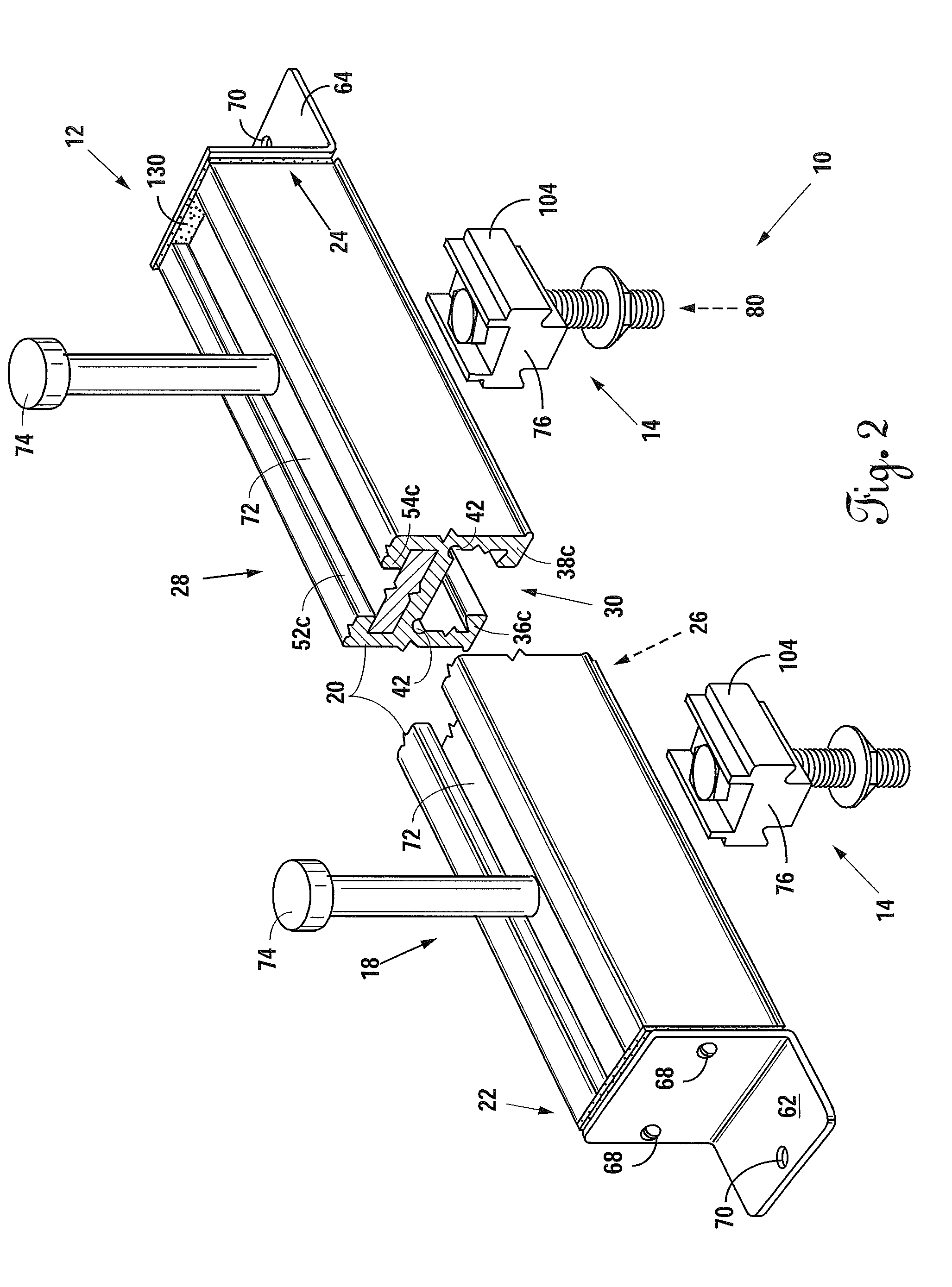
[0041]Referring to FIGS. 1 and 2, perspective views of the preferred embodiment of a cast-in anchor system 10 of the present invention are shown. In general, the cast-in anchor system 10 has a cast-in anchor assembly 12 engaged with one or more bolt-retainer assemblies 14. The cast-in anchor assembly 12 and the bolt-retainer assembly 14 each have various components and are individually discussed herein below.

[0042]The cast-in anchor assembly 12 has a cast-in anchor 16 attached to a base assembly 18. The cast-in anchor 16 is a length of material 20 extending from a first end 22 to a second end 24. Although the preferred length of material 20 is an extruded aluminum alloy, it could be made from any number of materials, whether extruded or not. The length of material 20 has a first side 26 and a second side 28 separate from the first side 26. An anchor channel 30 extends at least partially along its first side 26 and a plate channel 32 extends at least partially along its second side 2...


PUM

PropertyMeasurementUnit
angleaaaaaaaaaa
lengthaaaaaaaaaa
lengthsaaaaaaaaaa

Abstract

A cast-in anchor system for anchoring objects to concrete structures. The preferred system uses an extruded cast-in anchor and an extruded bolt retainer. The cast-in anchor is embedded within concrete with a face left exposed. The bolt retainer has a bolt inserted through it and is placed within an anchor channel on the exposed face of the cast-in anchor. The bolt retainer allows for use of an industry-standard bolt and prevents the bolt from rotating once the bolt-head is seated against it. The cast-in anchor and the bolt are positioned along the length of the anchor channel, with a threaded portion of the bolt extending out of the anchor channel. A workpiece is placed over the threaded portion of the bolt and a nut is tightened. Tightening the nut causes locking surfaces on the bolt retainer to engage with corresponding surfaces on the anchor channel which prevents the bolt retainer from exiting the anchor channel.

Description

BACKGROUND OF THE INVENTION[0001]1. Field of the Invention[0002]The present invention relates generally to improved concrete cast-in anchor systems and improved methods of manufacturing of the various components of these systems. More specifically, the preferred embodiment of the present invention relates to a cast-in anchor system partially made of extruded components and which allows for use of industry-standard bolts to operate the system, rather than specialty bolts.[0003]2. Description of the Related Art[0004]Cast-in anchor systems are one of a variety of ways to anchor objects to concrete structures. These systems are particularly advantageous because they provide diverse anchoring solutions, able to anchor many different items. For example, these systems may be used to anchor heavy equipment within a building or curtain wall systems to the exterior of a building.[0005]In general, traditional cast-in anchor systems use an embedded cast-in anchor engaged with one or more retain...

Claims


Application Information

Patent Timeline
Patent Type & Authority Applications(United States)
IPC IPC(8): E04B1/41F16B41/00
CPCF16B41/002E04B1/4107F16B7/187Y10T29/49826
Inventor RICHARDSON, DOUGLAS S.
Owner RICHARDSON DOUGLAS S
Why Eureka
Try Eureka