Method and apparatus for achieving a high efficiency in an open gas-turbine (combi) process

a gas turbine and open gas technology, applied in the direction of combined combustion mitigation, turbine/propulsion fuel heating, steam engine plants, etc., can solve the problems of high energy loss of waste heat boilers, steam turbine processes, and inability to achieve high efficiency, so as to achieve a smaller energy loss and great efficiency.

Inactive Publication Date: 2014-09-11
LOYTTY ARI
View PDF6 Cites 4 Cited by
  • Summary
  • Abstract
  • Description
  • Claims
  • Application Information

AI Technical Summary

Benefits of technology

[0019]The 0.5 bar referred to in the claims is not an optimum point and expansion taking place to about 0.2 bar, shown in Table 1, will lead to a greater efficiency. Similarly, the water vapor arising in combustion in an open (or closed) gas-turbine process or STIG process condenses into liquid at atmospheric pressure. In the process according to the invention, the water vapor arising in combustion condenses into liquid at a pressure lower than atmospheric pressure, so that the energy loss is smaller.

Problems solved by technology

In existing combi processes incorporating two combustion chambers, a higher efficiency is not achieved.
The reason for this is not easy to determine, but closer investigation of the matter shows that the energy loss of the waste-heat boiler is great, because the exhaust temperature of the combustion gases after the second combustion chamber is high.
In addition, this US patent in question does not have a steam-turbine process.

Method used


Image

  • Method and apparatus for achieving a high efficiency in an open gas-turbine (combi) process
  • Method and apparatus for achieving a high efficiency in an open gas-turbine (combi) process
  • Method and apparatus for achieving a high efficiency in an open gas-turbine (combi) process

Examples


Embodiment Construction

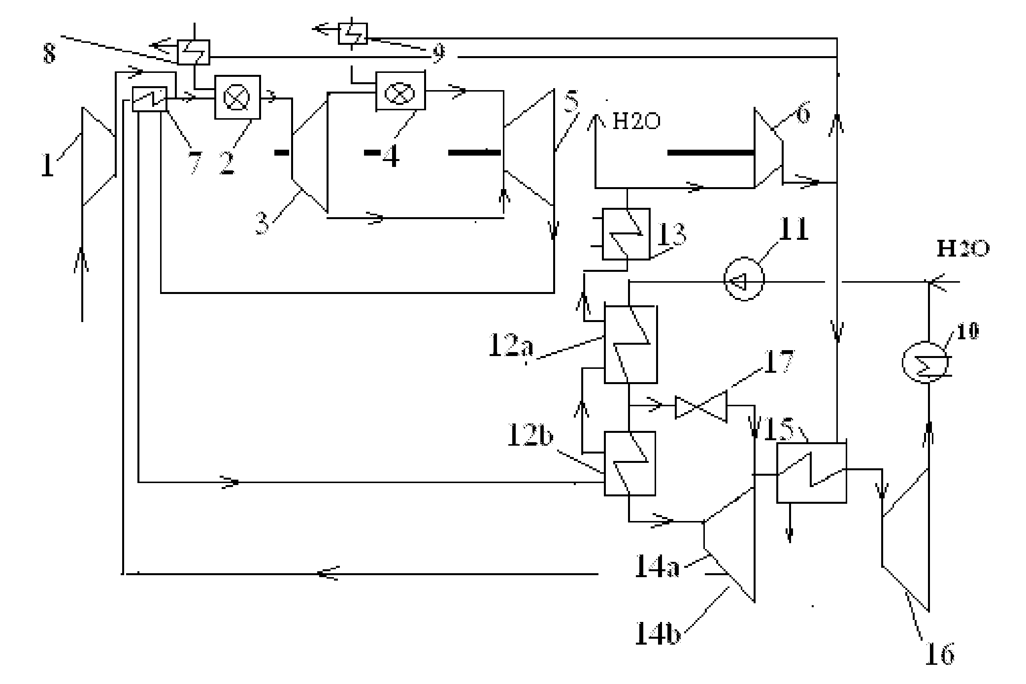
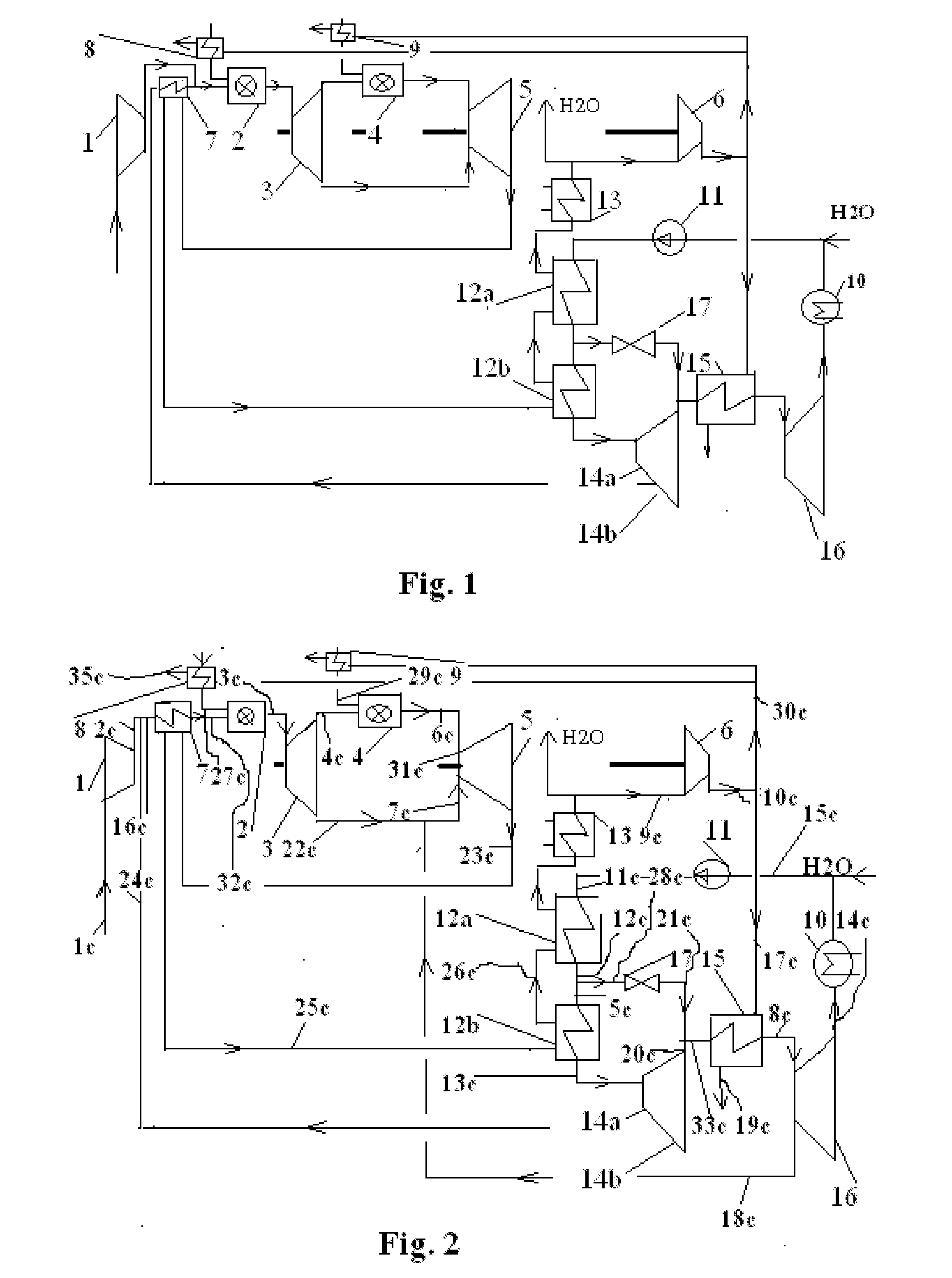
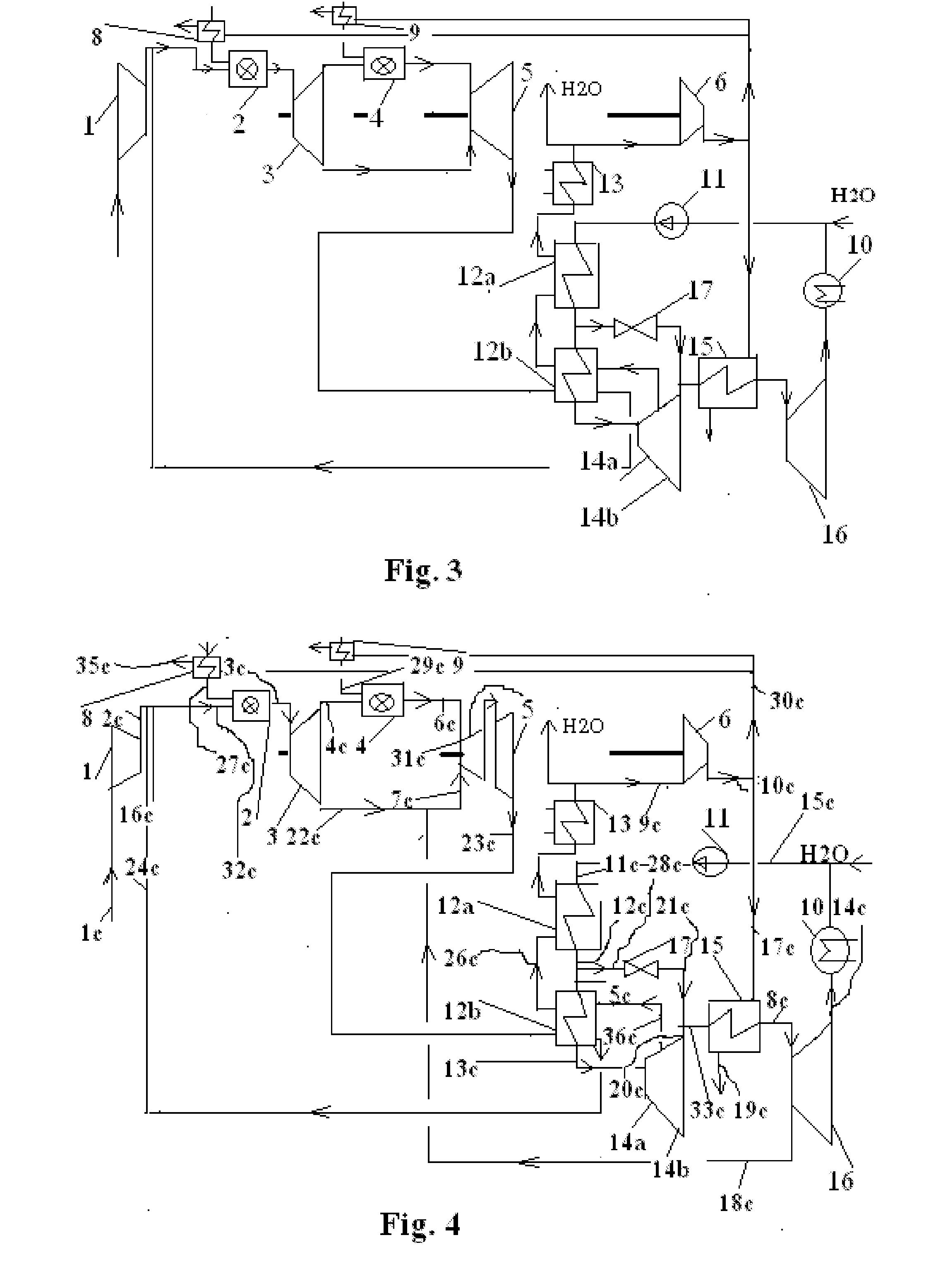
[0032]FIG. 1 shows an open gas-turbine (combi) process, in which a supercharger (1) compresses air, which is burned with fuel in a first combustion chamber (2), which is followed by a first turbine (3), a second combustion chamber (4), a second turbine (5), and a preheating heat exchanger (7), in which primary bleed steam coming from the secondary process is preheated.

[0033]The combustion gases go from the preheating heat exchanger (7) to a waste-heat boiler (12a, b), in which the feed water of the secondary process is vaporized. For reasons of clarity, the water-heat boiler is shown in two parts (12a, b), though in reality it consists of a single heat exchanger. Preheating of the maximum-pressure water takes place mainly in waste-heat boiler (12a) and vaporization and superheating mainly in waste-heat boiler (12b). The combustion gases expand in the second turbine (5) to a pressure lower than that of the surrounding atmospheric pressure, when the combustion gases remaining after th...


PUM


Abstract

Method and apparatus for achieving high efficiency in an open gas-turbine process, in which a supercharger compresses air, which is burned together with a fuel in a first combustion chamber, which is followed by a first turbine, a second combustion chamber, a second turbine, and a preheating heat exchanger, in which primary bleed water vapor coming from the secondary process, or a mixture of the aforementioned water vapor and air coming from the supercharger are preheated. From the heat exchanger the combustion gases go to a waste-heat boiler, in which the secondary-process feed water is vaporized. The combustion gases are expanded in the second turbine to a pressure 0.5 bar lower than that of the surrounding atmospheric pressure. The remaining combustion gases are compressed by a combustion-gas supercharger to the surrounding atmospheric pressure. After the low-pressure turbine the water vapor is condensed in a condenser into water, which is compressed by a pump to a maximum pressure and is preheated and vaporized in the waste-heat boiler. After the waste-heat boiler the water vapor goes to a combined high/medium-pressure turbine, from which a secondary-process primary bleed is taken, which is injected into the gas-turbine process after the preheating heat exchange after the supercharger and/or at the latest to the start of the blades of the first turbine.

Description

FIELD OF INVENTION[0001]The invention relates to a method and apparatus for achieving a high efficiency in an open gas-turbine (combi) process.BACKGROUND OF INVENTION[0002]In existing gas-turbine combi processes, a supercharger compresses air, which is burned with fuel in a combustion chamber, which is followed by a turbine and a waste-heat boiler, in which water of the secondary-process circulation is vaporized. In the secondary-process circulation there is normally a vapor process, which, in the newest large plants, uses reheating of the water vapor. In the secondary process, after a low-pressure turbine, the water vapor condenses in a condenser into water, which is compressed by a pump to a maximum pressure, and preheated and vaporized in the waste-heat boiler. After the waste-heat boiler, the water vapor goes to the steam turbines of the process circulation.[0003]Using natural gas as the fuel, electricity is nowadays generally produced in a combined gas-turbine-steam power-plant...

Claims


Application Information

Patent Timeline
Patent Type & Authority Applications(United States)
IPC IPC(8): F01K23/10
CPCF01K23/106F01K23/10Y02E20/14F01K23/06F02C6/006F02C6/18F02C7/224
Inventor LOYTTY, ARI
Owner LOYTTY ARI
Why Eureka
Try Eureka