Fuel injection method and combustion engine with early pre-injection

a fuel injection and combustion engine technology, applied in the direction of machines/engines, combustion-air/fuel-air treatment, electric control, etc., can solve the problems of increasing the emissions of pollutants and greenhouse gases, reducing the efficiency of combustion, and relatively intense combustion, so as to reduce the emissions of the environment and increase the efficiency of combustion

Inactive Publication Date: 2014-09-11
ECOMOTORS
View PDF0 Cites 26 Cited by
  • Summary
  • Abstract
  • Description
  • Claims
  • Application Information

AI Technical Summary

Benefits of technology

[0017]Preferably, the pre-injected fuel is heated and pressurized to assume supercritical conditions prior to pre-injecting. When supercritical fuel is injected as a pre-injection during the intake stroke between 360° to 180° BTDCF the temperature and pressure in the cylinder results in the fuel condensing into liquid droplets. The condensed fuel droplets have droplet sizes much lower than is achieved by liquid fuel injection. During the compression stroke the fuel and air mixture is compressed and heated which results in the rapid evaporation and mixing of the fuel with the air. When supercritical fuel is injected as an ignition-injection during the compression stroke and the temperature and pressure in the cylinder are above those of the supercritical fuel temperature the fuel mixes with the air and remains in the supercritical condition.
[0023]Preferably, the fuel injection method comprises dividing the pre-injection into a series of small individual pre-injection shots. This stretches the pre-injections over a range of angles during the intake stroke and possibly extending into the compression stroke. Small individual pre-injection shots at varying angles during the intake stroke can be beneficial to fuel distribution in the cylinder resulting in improved fuel mixing with air and reduced exhaust emissions.
[0024]Preferably, the pre-injection starts as early as right after closing of the exhaust valve during the intake stroke at an angle between 355 and 345° before dead center BTDCF. Optimum start of injection is typically around 270° BTDCF since at this location the piston has maximum velocity and the intake air flow also has maximum velocity and mixing potential. Injecting earlier in the cycle has reduced velocities and also a smaller amount of the total charge is available for mixing with the fuel. Injecting later in the cycle results in reducing intake air velocities, an increased proportion of the intake charge mass becoming available and a later completion of the injection process. The latter reduces the mixing time of the fuel with the air before combustion thus compromising the mixture quality. Optimization of the start of injection is therefore subject to complex interactions is carried out experimentally.

Problems solved by technology

Most gasoline and diesel car engines are only 20-30% efficient, such that a major portion of the hydrocarbon fuels is wasted, thereby depleting global resources while producing an excessive quantity of pollutants and greenhouse gases.
While the premixed combustion is relatively effective, some problems might arise from this relatively intense combustion over a relatively short angle.
For instance, noise might be generated by the premixed combustion.
As a practical solution, 2 types of fuel are typically not acceptable, for instance for motor vehicles as it requires 2 fuel tanks and 2 different types of injectors.

Method used


Image

  • Fuel injection method and combustion engine with early pre-injection
  • Fuel injection method and combustion engine with early pre-injection
  • Fuel injection method and combustion engine with early pre-injection

Examples


Embodiment Construction

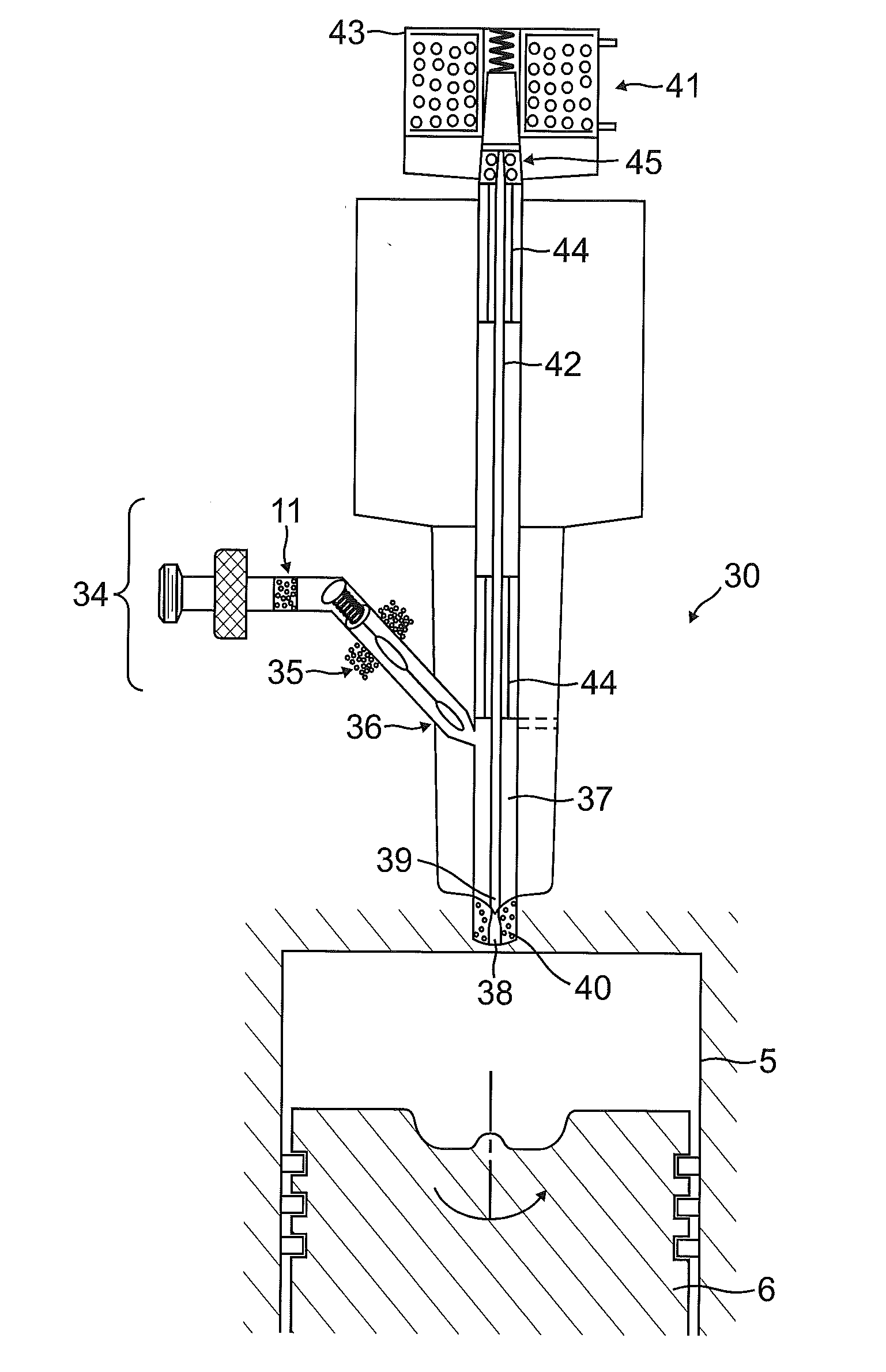
[0016]Preferably, the pre-injected fuel charge during the intake stroke can be between 10 and 20% of the total fuel charge, but also other ranges like between 20 and 30% of the fuel charge is pre-injected during the intake stroke or between 30 and 50% of the fuel charge is pre-injected during the intake stroke or between 50 and 90% of the fuel charge is pre-injected during the intake stroke are possible. Start of injection timing of the pre-injected fuel can be in the range 360° to 180°BTDCF. Similarly the injected fuel charge during the compression stroke, also known as the ignition-injection, can be up to 90% of the total fuel charge injected during the intake and compression cycle. Start of injection ignition timing can be in the range 180° to 360° BTDCF. Accordingly, with late timing of the ignition-injection it is possible for the ignition-injection to continue after TDCF until such time as the injection is complete.

[0017]Preferably, the pre-injected fuel is heated and pressuri...


PUM


Abstract

A fuel injection method in an internal combustion engine and an internal combustion engine for performing the fuel injection method. The method includes heating fuel to a temperature between 300° F. and 840° F. (150 and 450° C.); pressurizing the fuel to a pressure exceeding 40 bar; pre-injecting at least 10% of the fuel charge as a pre-injected fuel during the intake stroke; injecting a fuel charge over at least part of the compression stroke into the cylinder; and injecting an ignition-injection of at least 10% of the fuel in a supercritical condition during the compression stroke at a rotational angle between 90° BTDCF and TDCF into the cylinder. The method and related combustion engine create a good mix of premix combustion and diffusion combustion increasing efficiency and consequently reducing emissions to the environment while also keeping noise and vibrations low.

Description

TECHNICAL FIELD[0001]The present invention relates to a fuel injection method in an internal combustion and an internal combustion engine implementing the fuel injection method.DESCRIPTION OF THE RELATED ART[0002]Much of the world's energy consumption is dedicated to powering internal combustion based vehicles. Most gasoline and diesel car engines are only 20-30% efficient, such that a major portion of the hydrocarbon fuels is wasted, thereby depleting global resources while producing an excessive quantity of pollutants and greenhouse gases. With hydrocarbon fuels becoming more scare and more expensive it is desirable to obtain more efficient use of those fuels.[0003]Internal combustion engines typically use one or more fuel injectors to inject fuel into a combustion chamber of the engine. Typical fuel injectors may have hydraulically, electromagnetically, or piezoelectrically actuated injector pins. A piezoelectric element is a material that changes dimensions when a voltage is app...

Claims


Application Information

Patent Timeline
Patent Type & Authority Applications(United States)
IPC IPC(8): F02M31/02
CPCF02M31/02F02B51/00F02D41/3047F02D41/402Y02T10/12Y02T10/40F02D41/30F02D41/38F02M53/06
Inventor DE BOER, CHRISTOPHERSASAKI, SHIZUO
Owner ECOMOTORS
Why Eureka
Try Eureka