Injection quill designs and methods of use

a technology of injection quills and quills, which is applied in the direction of transportation and packaging, mixing, chemistry apparatus and processes, etc., can solve the problems of severe corrosion of exposed pipe surfaces, uneven coverage of processing equipment surfaces, and uneven distribution of treatment chemicals, so as to improve the coating process and improve the dispersion process , increase the volume fraction of the filmer

Inactive Publication Date: 2016-09-15
BL TECH INC
View PDF4 Cites 10 Cited by
  • Summary
  • Abstract
  • Description
  • Claims
  • Application Information

AI Technical Summary

Benefits of technology

[0007]The injection quill designs may be used to coat a pipe wall with a filmer or to disperse a chemical treatment, such as a scavenger, in a hydrocarbon stream. When coating a pipe wall or other processing equipment, the coating process may be improved by increasing the volume fraction of the filmer (“treatment chemical” or “first fluid”) on the pipe walls along the length of the pipe. The dispersion process may be improved by inducing homogeneous mixing of the treatment chemical with the process stream. This may be achieved by a combination of various means, such as increasing the turbulence of the process stream, adjusting the particle size distribution of the treatment chemical, increasing the coverage area of the treatment chemical, etc. Injecting the treatment chemical in regions of high velocity regions of the fluid being treated (“process stream” or “second fluid”) also aids in homogenous mixing as the process stream can act as a carrier to carry the treatment chemical farther and faster. In some cases, decreasing the average droplet size of the chemical treatment may also improve the chemical treatment's efficiency. The disclosed designs may be used to coat a pipe wall with a filmer, or disperse a treatment chemical, such as a scavenger, in a hydrocarbon stream. It was also surprisingly discovered that the injection quill designs increase the volume fraction of the first fluid along the length of a pipe, while at the same time, minimize the pressure drop in the process stream being treated.

Problems solved by technology

This current method may be sub-optimal, leading to uneven distribution of treatment chemicals or uneven coverage of processing equipment surfaces.
In the cases where the treatment chemical is a corrosion inhibitor, such uneven coverage may lead to severe corrosion of exposed pipe surfaces, as witnessed in the field.
This trial and error process is inefficient and costly.
In addition, injection quills obstruct the flow of the process stream being treated.
The obstruction may be enough to cause a pressure drop in the process stream being treated.

Method used


Image

  • Injection quill designs and methods of use
  • Injection quill designs and methods of use
  • Injection quill designs and methods of use

Examples


examples

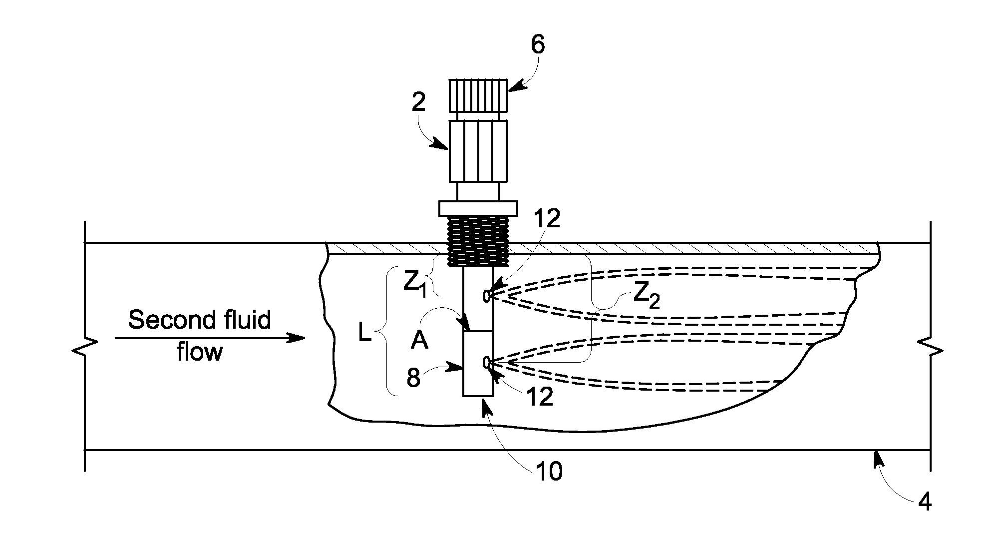
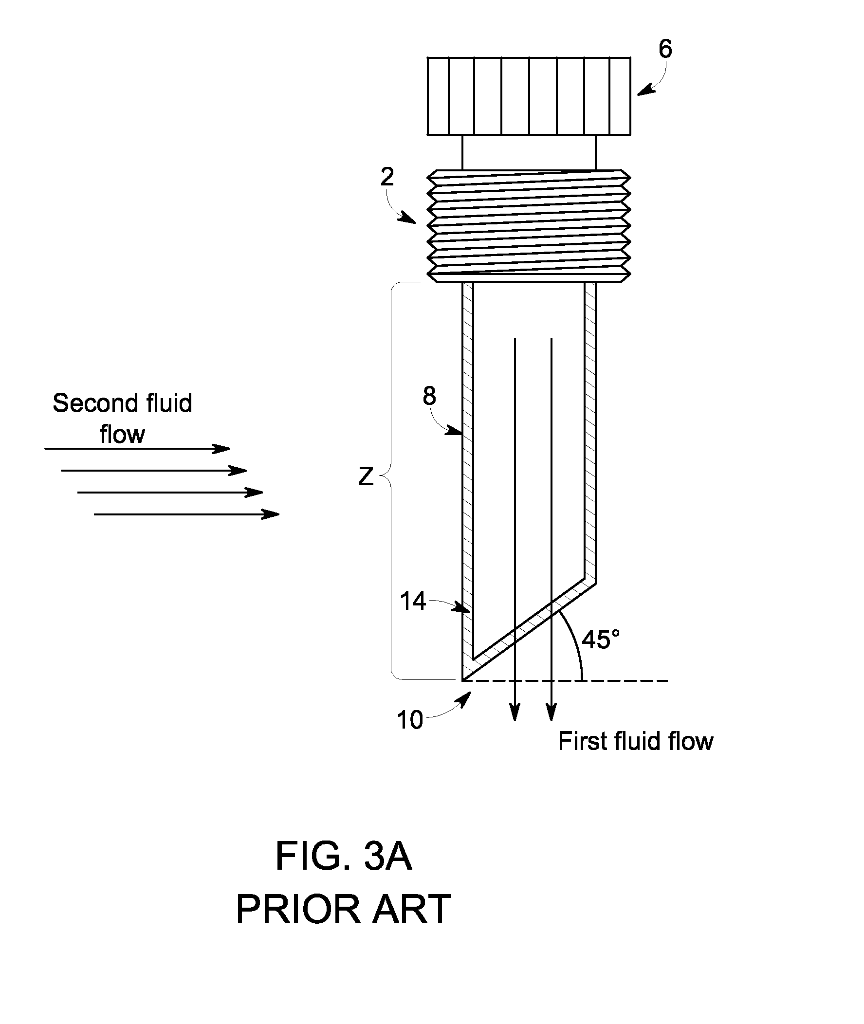
[0108]The injection quill designs may be used to coat a pipe wall with a filmer or to disperse a chemical treatment, such as a scavenger, in a hydrocarbon stream. When coating a pipe wall or other processing equipment, the coating process may be improved by increasing the volume fraction of the filmer (“first fluid”) on the pipe walls along the length of the pipe. Thus, the volume fraction (VF) of naphtha was evaluated using different quill designs. When dispersing a chemical treatment throughout a process stream, the dispersion process may be improved by minimizing the decrease in velocity of the process stream being treated (“second fluid”) caused by the stem and when injecting the first fluid. Thus, the fluid velocity was also evaluated using different quill designs.

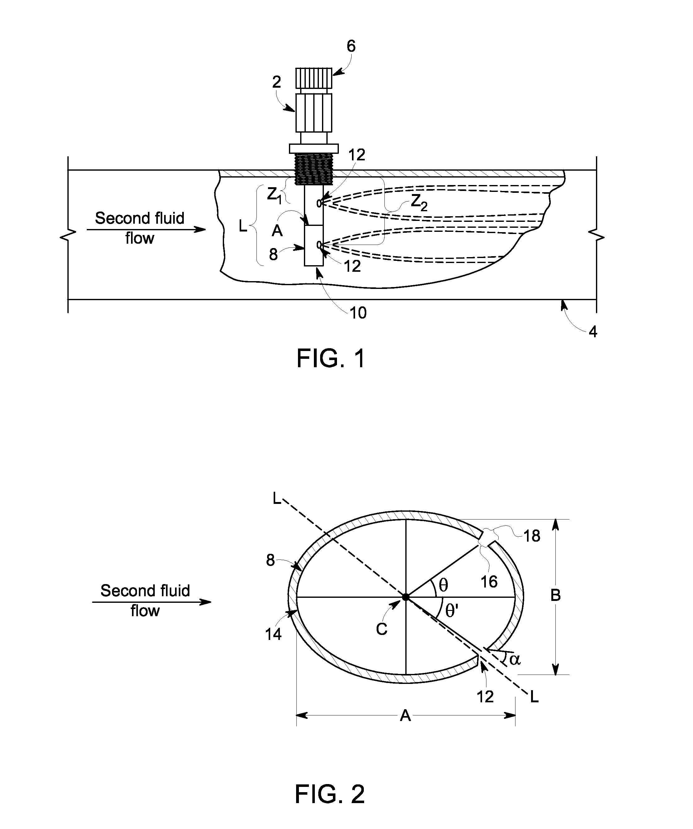
[0109]For the examples, the effects of location angle θ, the chamfer angle (α), and the number of orifices, on volume fraction and fluid velocity were simulated using Computational Fluid Dynamics (“CFD”) model. Multip...

example set 1

Number of Orifices

[0111]Example Set 1 shows the effects of the number of orifices on the volume fraction of naphtha and velocity of the fluid in the pipe. The effects were simulated for a stem with two orifices and compared with a stem with four orifices. The inner diameter (16) of the orifice was ⅛″. The chamfer angle (α) was 60° and the chamfer length was 0.226″, the entire thickness of the stem sidewall (14). The orifice location angles θ and θ′ were 75° and −75° respectively for all the simulations in Example Set 1.

[0112]For the simulations with two orifices, the distance (z) for the two orifices was 12″ from the pipe wall. For the simulations with four orifices, the distance (z1) for the first orifice pair was six inches from the pipe wall and the distance (z2) for the second orifice pair was 12 inches from the pipe wall. The data for the two-orifice and four-orifice simulations are summarized in Table 1 below.

TABLE 1volumetricflow rationatural gasnatural(naphtha / locationnaphth...

example set 2

Chamfer Angle

[0114]Example Set 2 shows the effects of the chamfer angle (α) on the volume fraction (VF) of naphtha and velocity of the fluid in the pipe. The effects were simulated for a stem with one orifice located at θ=0° and z=12″. The inner diameter (16) of the orifice was ⅛″ and stem sidewall (14) thickness was 0.226″. The chamfer length was the entire thickness of the stem sidewall, i.e., 0.226″. The chamfer angles (α) tested were 7.3°, 30°, 60°, and 70°. The data for the chamfer angle simulations are summarized in Table 2 below.

TABLE 2volumetricflow rationatural gasnaphthanatural gas(naphtha / locationnaphthavelocityFRFRnatural(m)VF(m / s)(kg / s)(kg / s)gas)α = 7.3°; Naphtha Volume Fractionon Pipe Wall = 1.97E−11x = 3.073.15E−0619.11.95E−095.30E−043.386E−09 x = 41.79E−0718.96.36E−071.10E−035.31E−07x = 51.77E−0719.08.81E−072.00E−034.05E−07x = 61.74E−0718.92.07E−065.70E−033.34E−07x = 71.73E−0718.92.03E−066.80E−032.74E−07x = 81.72E−0718.92.29E−067.80E−032.70E−07x = 91.72E−0719.01.95E−...


PUM

PropertyMeasurementUnit
chamfer angleaaaaaaaaaa

Abstract

An injection quill design and methods of use for injecting a first fluid into a second fluid. The injection quill may comprise a hollow stem having a closed end and a sidewall, the stem having a curved cross-section defined by a major axis, and a minor axis, and at least one orifice for injecting the first fluid into the second fluid, wherein the major axis is greater than the minor axis and/or the orifice extends through the sidewall and/or the orifice has an internal chamfer with a chamfer angle ranging from less than 0° but greater than 90°.

Description

BACKGROUND[0001]1. Field of the Invention[0002]The subject matter disclosed herein generally relates to an apparatus for injecting a first fluid into a second fluid. More specifically, an injection quill design and methods of use are disclosed.[0003]2. Description of Related Art[0004]In refineries, water treatment facilities, and other process industries, chemical treatments are used to reduce or deactivate harmful species in process streams and protect processing equipment from corrosion and fouling. This involves injecting the treatment chemical into the process stream. Both the treatment chemical and process stream may be oil-soluble, water-soluble or a mixture thereof. The treatment chemicals and process streams may be a liquid, gas, or a mixture thereof. Uniform and maximum dispersion of the treatment chemical through the process stream may increase the effectiveness of the treatment chemical and may even reduce treatment costs. Likewise, uniform and maximum volume fraction of ...

Claims


Application Information

Patent Timeline
Patent Type & Authority Applications(United States)
IPC IPC(8): B01F5/04C10G75/00B01F3/08B01F25/70
CPCB01F5/0463C10G75/00B01F3/0865B01F2215/0404B01F2215/0422B01F2215/0431B01F25/3133B01F25/31331B01F23/451
Inventor KENRECK, JR., GLENN VERNONRADHAKRISHNAN, JAYAPRAKASH SANDHALAJOSHI, MANISHKOTA, SIVA KUMAR
Owner BL TECH INC
Why Eureka
Try Eureka