Two-phase projectile with a proximal compression chamber

a compression chamber and projectile technology, applied in the field of man-powered devices, can solve the problems of increasing the velocity of one component and discharging the velocity of the other component, and achieve the effect of easy removal

Inactive Publication Date: 2014-09-11
FLINT G WILSON +1
View PDF0 Cites 6 Cited by
  • Summary
  • Abstract
  • Description
  • Claims
  • Application Information

AI Technical Summary

Benefits of technology

[0007]Structurally, a device for the present invention includes a first component that is tubular shaped and is formed with a lumen which defines an axis. Further, the first component has an open end and a closed end. Also included in the device of the present invention is a second component that is engaged with the first component to create an assembly. Specifically, this assembly establishes a gas-filled compression chamber in the lumen of the first component that is located between the second component and the closed end of the first component. Within this combination, the assembly allows for a substantially free axial movement of the second component back and forth in the compression chamber of the assembly. Further, depending on the embodiment of the present invention, a payload is selectively mounted on a component of the assembly. For the present invention, the payload may be either a conventional arrow (e.g. a broadhead) as used with a vertical bow (launcher), a bolt as used with a crossbow (launcher), or a shot cluster that may be adapted for use by either type launcher.
[0008]As envisioned for the present invention, a man-powered launcher will be used to generate an axially-directed driving force on one component of the assembly (projectile) in order to propel the projectile from the launcher and onto its flight path. A consequence of this driving force is to cause a relative movement between the first component and the second component. Recall, the second component is free to move within the lumen of the first component (i.e. it is free to move within the gas chamber of the assembly). In the event, this movement further compresses gas in the compression chamber to thereby increase potential energy in the compressed gas.
[0019]Additionally, the cartridge includes a friction collar that is positioned in a snug engagement against the outer surface of the cartridge. The purpose of this friction collar is to generate friction forces against the cartridge that will retard movement of the cartridge during the separation of the pellet cluster from the cartridge. In particular, the friction collar is preferably made of aluminum and it will exert a radial pressure against the cartridge of approximately 500 psi. Further, a slide ring assembly is positioned on the outer surface of the cartridge, distal to the friction collar. The purpose here is to mitigate impact forces against the friction collar at the launch of the pellet cluster.
[0021]The propulsion shaft further includes a pressure valve that is positioned at the proximal end of the propulsion shaft. As envisioned for the present invention, the pressure valve will be mounted in a nock, and the nock will be affixed to the proximal end of the propulsion shaft for operational interaction with the launcher of the projectile assembly. Specifically, the purpose of the pressure valve is to allow the compression chamber to be pressurized to a predetermined gauge pressure (e.g. 80 psig) prior to imparting the driving force against the shaft, to thereby provide an initial level of resistance to the compression of gas in the compression chamber.
[0022]As an added feature for the projectile assembly, a ferrule is attached to the distal end of the propulsion shaft. In particular, the ferrule has a threaded extension projecting in a distal direction from the distal end of the shaft. A plug can then be joined in a threaded engagement with the ferrule to create an abutment around the open distal end of the propulsion shaft. This abutment then establishes a distal limit for movement of the cartridge in the lumen of the shaft. Also, because the plug is in a threaded engagement with the propulsion shaft, it can be easily removed for the replacement of a spent cartridge.

Problems solved by technology

This causes a resultant increase in the velocity of one component, and a resultant dissipation in the velocity of the other component; a combination of events that separates the payload from the assembly.

Method used


Image

  • Two-phase projectile with a proximal compression chamber
  • Two-phase projectile with a proximal compression chamber
  • Two-phase projectile with a proximal compression chamber

Examples


Embodiment Construction

[0039]Referring initially to FIG. 1A, a device in accordance with the present invention is shown and is generally designated 10. As shown, the device 10 includes a projectile 12 and a man-powered launcher 14. In the particular case of the device 10 that is shown in FIG. 1A, the launcher 14 is a vertical bow of a type well known in the art. The launcher 14, however, could as well be a crossbow (not shown) or an air gun (not shown), both of which are of types well known in the pertinent art.

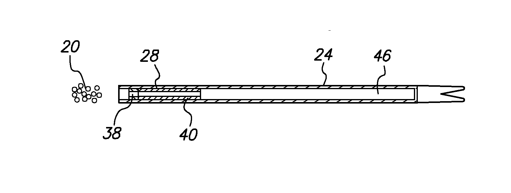
[0040]As illustrated sequentially in FIGS. 1A, 1B and 1C, a purpose of the present invention is to use the launcher 14 to propel the projectile 12 along a flight path (dashed line) 16 toward a target 18. In sequence, FIG. 1A shows the launcher 14 in a configuration for firing the projectile 12. FIG. 1B then shows the projectile 12 as it is being released from the launcher 14. And, FIG. 1C shows the projectile 12, and its payload 20 after it has been separated from the projectile 12 in flight, after...


PUM


Abstract

A man-powered system for pneumatically launching a pellet cluster includes a cartridge for holding the pellet cluster. A hollow propulsion shaft receives the cartridge for substantially free travel back and forth in the shaft to establish a variable-volume compression chamber in the shaft, between the cartridge and a closed end of the shaft. When a driving force acts to launch the combination of cartridge and shaft, the cartridge moves to compress gas in the compression chamber for a subsequent expansion that will propel the cartridge forward through the shaft. After launch, the compressed gas acts to separate the pellet cluster from the cartridge and to provide a pneumatic assist that increases the velocity of pellets after separation.

Description

[0001]This application is a continuation-in-part of application Ser. No. 13 / 789,514, filed Mar. 7, 2013, which is currently pending. The contents of application Ser. No. 13 / 789,514 are incorporated herein by reference.FIELD OF THE INVENTION[0002]The present invention pertains generally to man-powered devices for launching pellet clusters. More particularly, the present invention pertains to man-powered launchers that provide a pneumatic assist to pellets as they are being launched. The present invention is particularly, but not exclusively, useful as a man-powered device that provides, in combination, a cartridge for holding a pellet cluster and a propulsion tube for interacting with the cartridge to create compressed gas during a launch, to thereby provide a pneumatic assist for increasing the velocity for the pellets after they become separated from the cartridge.BACKGROUND OF THE INVENTION[0003]An important factor for evaluating the performance of a man-powered launcher is the ve...

Claims


Application Information

Patent Timeline
Patent Type & Authority Applications(United States)
IPC IPC(8): F41B11/70F42B12/58F42B6/02F41B11/73F41B11/72
CPCF41B11/73F42B6/02F42B12/58F42B12/64F41B11/723F42B10/38F42B6/04
Inventor FLINT, G. WILSONJONES, MICHAEL T.
Owner FLINT G WILSON
Why Eureka
Try Eureka