Millable Fracture Balls Composed of Metal

a technology of metal and fracture balls, which is applied in the direction of sealing/packing, other domestic objects, and well accessories, etc., can solve the problems of compromising the seating ability or the ability to float to the surface, aluminum balls b if left downhole can be particularly difficult to mill out of sliding sleeves, and long mill up times required per zon

Inactive Publication Date: 2014-09-11
WEATHERFORD TECH HLDG LLC
View PDF22 Cites 17 Cited by
  • Summary
  • Abstract
  • Description
  • Claims
  • Application Information

AI Technical Summary

Problems solved by technology

Any variations in pressuring up and down that allow the aluminum ball B to seat and to then float the ball B may alter the shape of the ball B, compromising its seating ability or its ability to float to the surface after use.
Additionally, aluminum balls B if left downhole can be particularly difficult to mill out of the sliding sleeve 10 due to their tendency of rotating during the milling operation.
One problem with using aluminum balls B can be the long mill up times required per zone.
For instance, milling just one frac stage when a solid aluminum ball is used can take up to an hour.
As are result, milling the seats 40 and aluminum balls B can be longer than desired, which delays operators' ability to put the well in production.
Yet, as noted previously, these non-metal balls may not hold the desired operating pressures and may not provide as many stages as can be obtained with the minimized aluminum ball and seat engagement.

Method used


Image

  • Millable Fracture Balls Composed of Metal
  • Millable Fracture Balls Composed of Metal
  • Millable Fracture Balls Composed of Metal

Examples


first embodiment

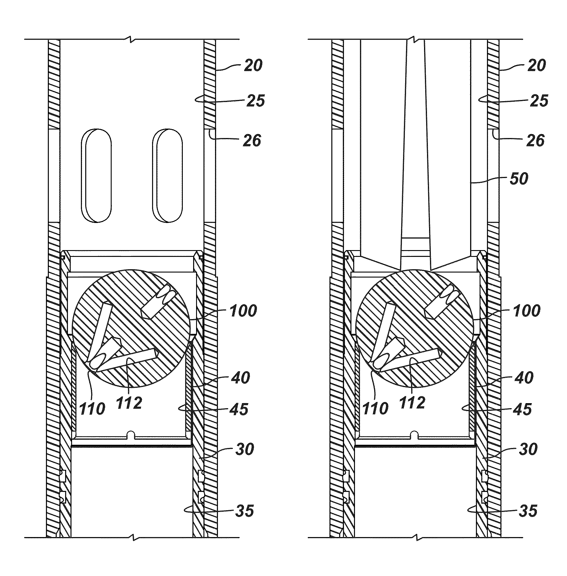
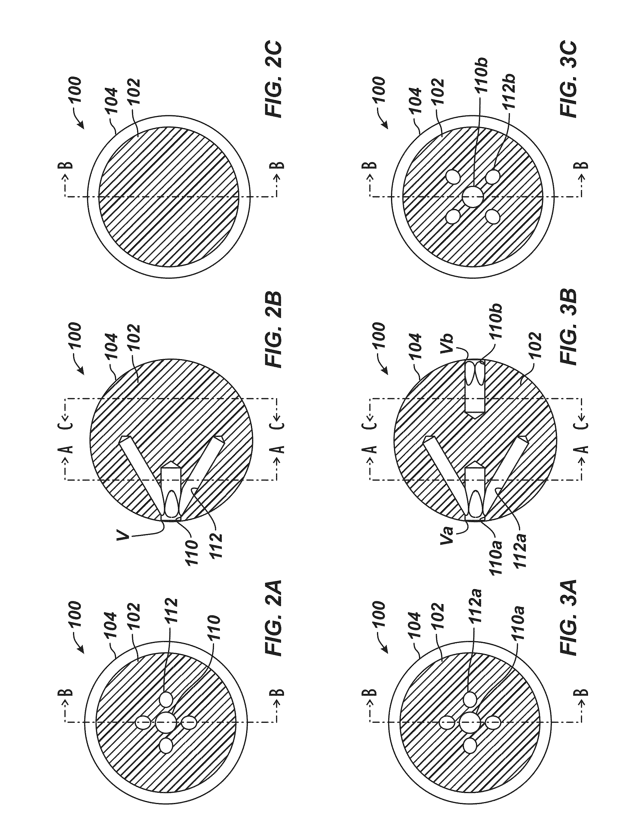
[0034]FIGS. 2A-2C illustrate cross-sectional views of a ball 100 according to the present disclosure for actuating a sliding sleeve. The ball 100 has a solid, spherical body 102 composed of a metallic material, including, but not limited to, aluminum, aluminum alloy, steel, brass, aluminum bronze, a metallic nanostructure material, cast iron, etc. The metallic material is preferably one that can be floated to the surface and can be milled if necessary. Of course, the ball 100 can be composed of any suitable material, even ceramics, plastics, composite materials, phenolics, Torlon, Peek, thermoplastics, or the like.

[0035]Voids, spaces, or holes are defined in the body 102 to facilitate milling of the ball 100 when disposed in a ball seat of a tool, such as a sliding sleeve. Because the ball 100 has the purposes of sealingly engaging the ball seat in the sliding sleeve, the ball 100 preferably is configured to maintain or produce a sufficient seal with the ball seat when seated therei...

second embodiment

[0040]FIGS. 3A-3C illustrate cross-sectional views of a ball 100 according to the present disclosure for actuating a sliding sleeve. This ball 100 is similar to that discussed previously, but tap holes 110a-b are defined in opposing sides of the ball's body 102. Each tap hole 110a-b has a plurality of angled holes 112a-b in a manner similar to that discussed previously. Preferably as shown, the angled holes 112a-b are offset from one another around the axis defined by the tap holes 110a-b so that the opposing holes 112a-b do not meet with one another inside the body 102. Because the tap holes 110a-b are offset 180-degrees on opposite sides, it is less likely that both will engage the edge of a seat when landed thereon.

[0041]As before, the tap holes 110a-b can primarily provide common vertices Va-Vb from which the opposing angled holes 112a-b can be formed so that multiple tap points do not need to be made in the ball's surface 104. The ball 100 in FIG. 3A-3C essentially defines hole...

third embodiment

[0042]FIGS. 4A-4C illustrate cross-sectional views of a metallic ball 100 according to the present disclosure for actuating a sliding sleeve. This ball 100 is similar to that discussed above with reference to FIGS. 2A-2C in that a tap hole 110 and angled holes 114 are defined in one side of the ball 100. Rather than having four angled holes as in the previous embodiment, this ball 100 has three angled holes 114 drilled at about every 120-degrees around the tap hole 110.

[0043]In other differences illustrated, the angled holes 112 can be drilled at a shallower angle from the tap hole 110. Additionally, the ends of the angled holes 112 can extend beyond the midpoint of the ball's body 102. Thus, the angled holes 112 extend nearly to the opposing side of the ball's body 102.


PUM

PropertyMeasurementUnit
metallicaaaaaaaaaa
anglesaaaaaaaaaa
sealing areaaaaaaaaaaa

Abstract

A ball is used for engaging in a downhole seat and can be milled out after use. The ball has a spherical body with an outer surface. An interior of the spherical body is composed of a metallic material, such as aluminum. The spherical body has a plurality of holes formed therein. The holes extend from at least one common vertex point on the outer surface of the spherical body and extend at angles partially into the interior of the spherical body.

Description

CROSS-REFERENCE TO RELATED APPLICATION[0001]This application claims the benefit of the U.S. Prov. Appl. 61 / 774,729, filed 8 Mar. 2013, which is incorporated herein by reference.BACKGROUND OF THE DISCLOSURE[0002]In a staged fracturing operation, multiple zones of a formation need to be isolated sequentially for treatment. To achieve this, operators install a fracturing assembly down the wellbore, which typically has a top liner packer, open hole packers isolating the wellbore into zones, various sliding sleeves, and a wellbore isolation valve. When the zones do not need to be closed after opening, operators may use single shot sliding sleeves for the fracturing treatment. These types of sleeves are usually ball-actuated and lock open once actuated. Another type of sleeve is also ball-actuated, but can be shifted closed after opening.[0003]Initially, operators run the fracturing assembly in the wellbore with all of the sliding sleeves closed and with the wellbore isolation valve open....

Claims


Application Information

Patent Timeline
Patent Type & Authority Applications(United States)
IPC IPC(8): E21B33/12
CPCE21B33/1204E21B34/14Y10T29/49Y10T29/49712E21B34/142
Inventor GARCIA, CESAR G.ROSSING, MICHAEL
Owner WEATHERFORD TECH HLDG LLC
Why Eureka
Try Eureka