Digital underreamer

a technology of underreamer and reamer, which is applied in the field of digital underreamer, can solve the problems of limited bha (including both bits and reamer), uneven penetration rate of reamer and drill bit, and inability to achieve the effect of modulating cutting aggressiveness and variable cutting aggressiveness

Inactive Publication Date: 2014-09-11
BP CORP NORTH AMERICA INC
View PDF2 Cites 11 Cited by
  • Summary
  • Abstract
  • Description
  • Claims
  • Application Information

AI Technical Summary

Benefits of technology

[0006]Various aspects of the disclosure can provide a drilling assembly which can be particularly useful in multi-layer drilling applications, for example. The drilling assembly can be, be part of, or include a bottom hole assembly, and can include a drill bit and a reaming subassembly having one or more reamers. One or more sensors, such as single-axis or multi-axis vibration sensors, mechanical load sensors (e.g., strain gauges, torque sensors, etc.), sonic sensors, or the like can be positioned in or proximal to the drilling assembly, and can provide information to a controller indicating when the mechanical load (e.g., weight and / or torque) on the reaming subassembly is different from the mechanical load on the drill bit. The reaming subassembly, in turn, can have a variable cutting aggressiveness, which can be modulated by an actuator in response to signals sent by the controller. The controller can thus determine when the mechanical load on the reaming subassembly is disproportionate to the mechanical load on the drill bit, and then modulate the cutting aggressiveness of the reaming subassembly accordingly.

Problems solved by technology

One challenge experienced in RWD applications can be a disparity between the rate of penetration of the reamer and the rate of penetration of the drill bit.
This challenge can be caused by the BHA extending across a boundary or transition between one formation layer and a subjacent formation layer, where the two layers have different hardnesses.
Accordingly, if the drill bit proceeds from a harder region into a softer region, while the reamer remains in the harder region, the rate of penetration of the BHA (including both bit and reamer) will be limited by the reamer rate of penetration, with little or no indication topside that the torque and weight on the reamer have increased, potentially causing vibration of the bit and excessive load on the reamer.
In the reverse situation, increased rock hardness at the drill bit, as compared to the rock hardness at the reamer, can result in undesired vibration and can slow the overall rate of penetration.

Method used


Image

  • Digital underreamer
  • Digital underreamer
  • Digital underreamer

Examples


Embodiment Construction

[0018]For simplicity and illustrative purposes, the principles of the present teachings are described by referring mainly to examples of various embodiments thereof. However, one of ordinary skill in the art would readily recognize that the same principles are equally applicable to, and can be implemented in, all types of information and systems, and that any such variations do not depart from the true spirit and scope of the present teachings. Moreover, in the following detailed description, references are made to the accompanying figures, which illustrate specific examples of various embodiments. Electrical, mechanical, logical and structural changes can be made to the examples of the various embodiments without departing from the spirit and scope of the present teachings. The following detailed description is, therefore, not to be taken in a limiting sense and the scope of the present teachings is defined by the appended claims and their equivalents.

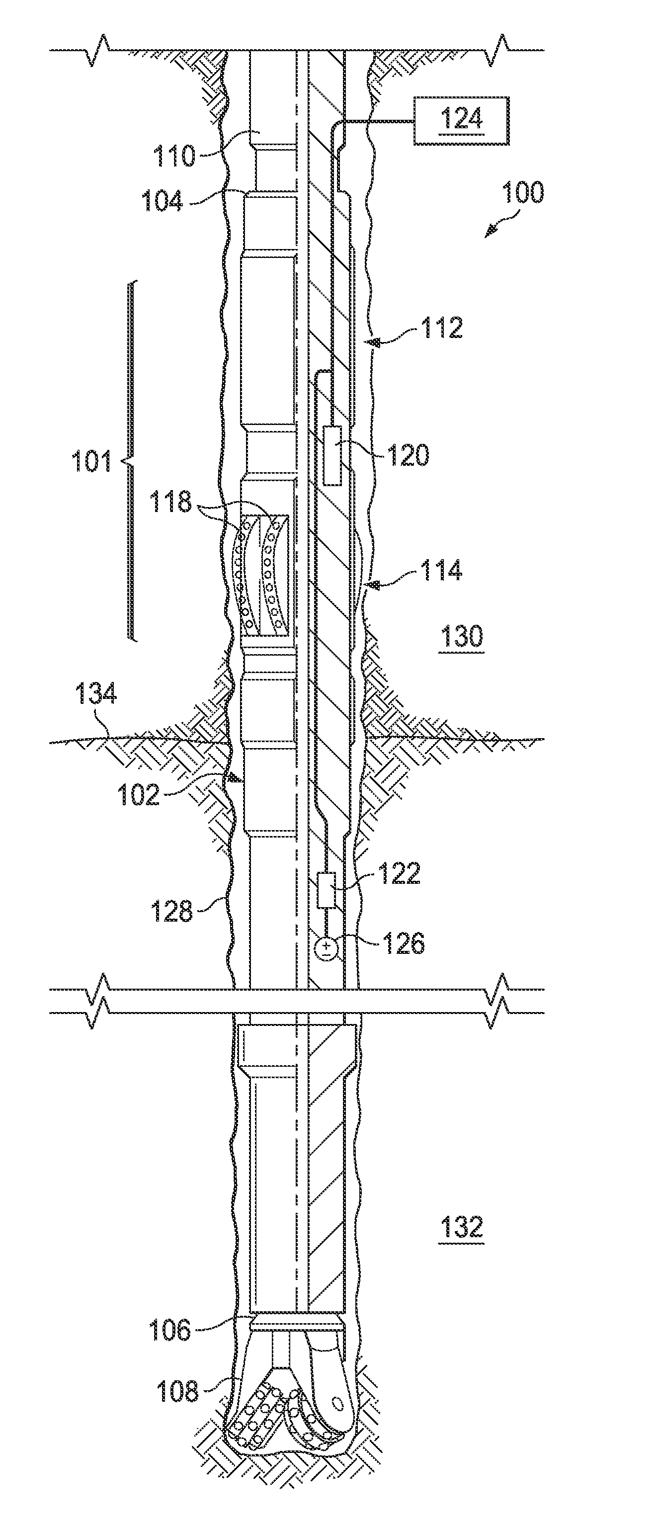
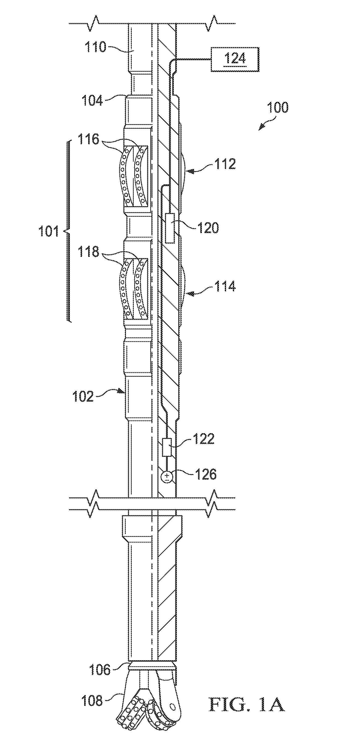
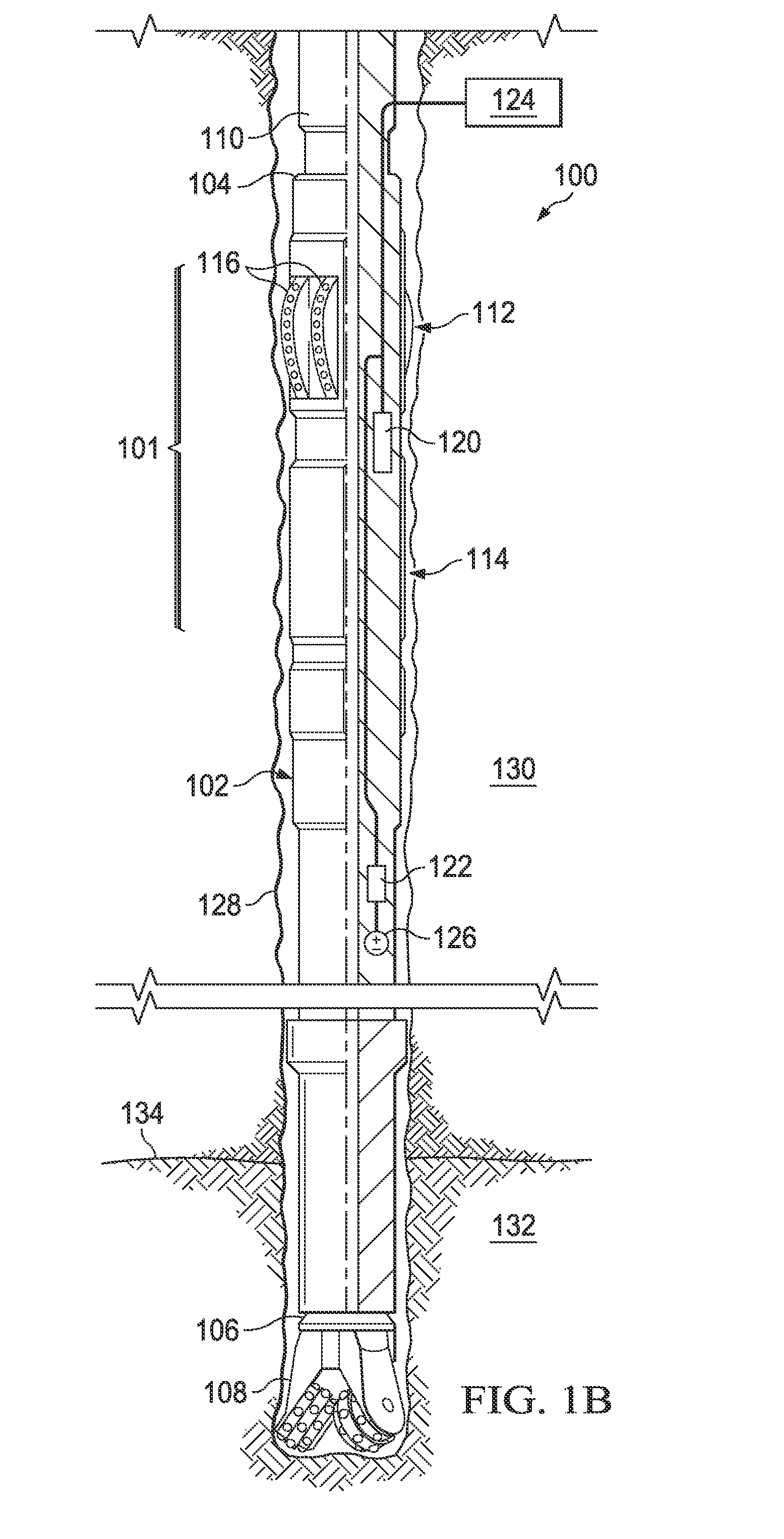
[0019]FIG. 1A illustrates a dr...


PUM


Abstract

Wellbore drilling apparatus and methods are provided. The apparatus includes a reaming subassembly including one or more reamers configured to ream a wellbore. The reaming subassembly defines a cutting aggressiveness that is variable while the reaming subassembly is disposed in a wellbore. The apparatus also includes an actuator coupled with the reaming subassembly and configured to vary the cutting aggressiveness of the reaming subassembly in response to an actuation signal.

Description

BACKGROUND[0001]Wellbores can be formed using a two step process whereby a pilot hole can be initially drilled using a drill bit and then radially expanded or “reamed” using a reamer. In some cases, multiple reamers can be used to ream the hole to a target diameter, step-wise, or one pass with a single reamer can be sufficient. This two-step process (drilling and reaming) can be employed for safety or efficiency reasons, or both. Further, the two steps can be performed by a single bottom hole assembly (BHA), such that the BHA both drills and reams the pilot hole in a single pass, as part of a process known as “reaming while drilling” (RWD).[0002]RWD applications include underreaming. In underreaming, the BHA passes through a reduced diameter section of the wellbore and then the reamer can be radially expanded and employed to provide an enlarged diameter section. Underreaming can be used, for example, to provide sufficient annular space for a casing liner, or for any other reason. Ty...

Claims


Application Information

Patent Timeline
Patent Type & Authority Applications(United States)
IPC IPC(8): E21B44/02E21B7/28
CPCE21B7/28E21B44/02E21B10/327
Inventor MCKAY, JAMES
Owner BP CORP NORTH AMERICA INC
Why Eureka
Try Eureka