
Jet Arrangement for a Downhole Drill Bit

Inactive Publication Date: 2007-06-07
SCHLUMBERGER TECH CORP
View PDF99 Cites 17 Cited by
  • Summary
  • Abstract
  • Description
  • Claims
  • Application Information

AI Technical Summary

Benefits of technology

[0002] The prior art has addressed bit whirl and weight on bit issues. Such issues have been addressed in the U.S. Pat. No. 6,443,249 to Beuershausen, which is herein incorporated by reference for all that it contains. The '249 patent discloses a PDC-equipped rotary drag bit especially suitable for directional drilling. Cutter chamfer size and backrake angle, as well as cutter backrake, may be varied along the bit profile between the center of the bit and the gage to provide a less aggressive center and more aggressive outer region on the bit face, to enhance stability while maintaining side cutting capability, as well as providing a high rate of penetration under relatively high weight on bit.
[0003] U.S. Pat. No. 6,298,930 to Sinor Ahich is herein incorporated by reference for all that it contains, discloses a rotary drag bit including exterior features to control the depth of cut by cutters mounted thereon, so as to control the volume of formation material cut per bit rotation as well as the torque experienced by the bit and an associated bottomhole assembly. The exterior features preferably precede, taken in the direction of bit rotation, cutters with which they are associated, and provide sufficient bearing area so as to support the bit against the bottom of the borehole under weight on bit without exceeding the compressive strength of the formation rock.

Problems solved by technology

Often drill bits are subjected to harsh conditions when drilling below the earth's surface.
Replacing damaged drill bits in the field is often costly and time consuming since the entire downhole tool string must typically be removed from the borehole before the drill bit can be reached.
Bit balling in soft formations and bit whirl in hard formations may reduce penetration rates and may result in damage to the drill bit.
Further, loading too much weight on the drill bit when drilling through a hard formation may exceed the bit's capabilities and also result in damage.
Too often unexpected hard formations are encountered suddenly and damage to the drill bit occurs before the weight on the drill bit may be adjusted.
A low whirling frequency accompanied by a high acceleration magnitude based on empirically established values is associated with destructive vibration of the filling component.

Method used


Image

  • Jet Arrangement for a Downhole Drill Bit
  • Jet Arrangement for a Downhole Drill Bit
  • Jet Arrangement for a Downhole Drill Bit

Examples


Embodiment Construction

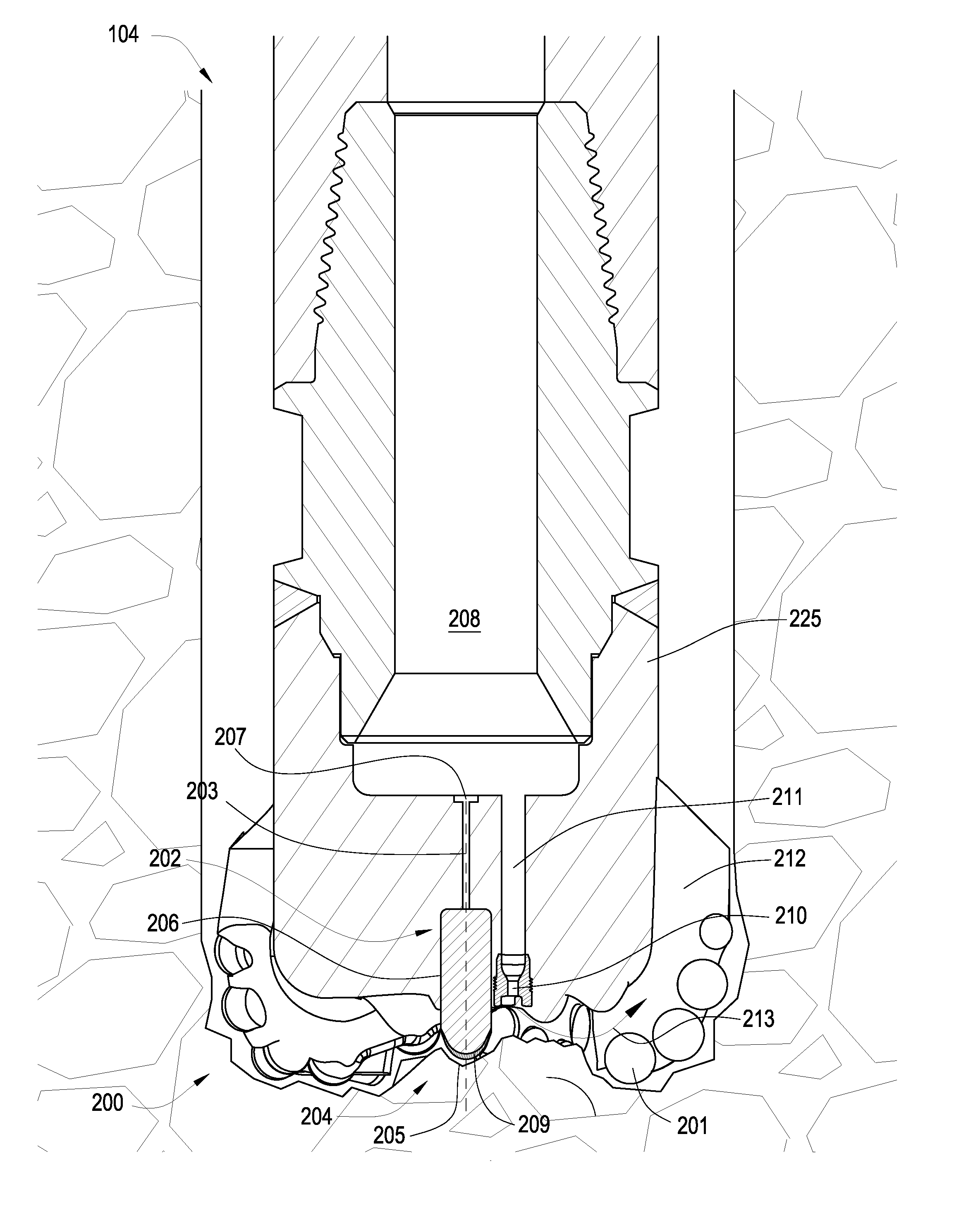
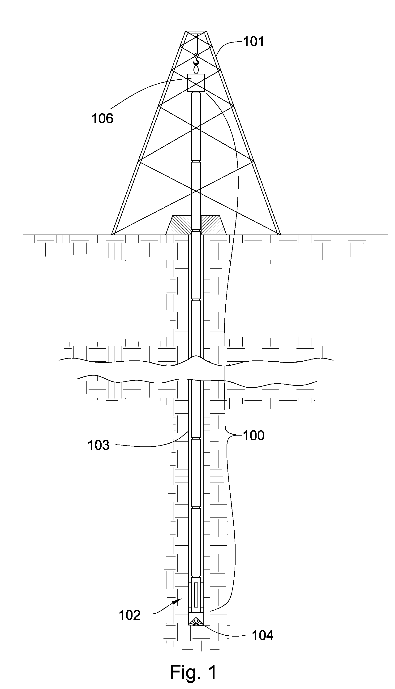
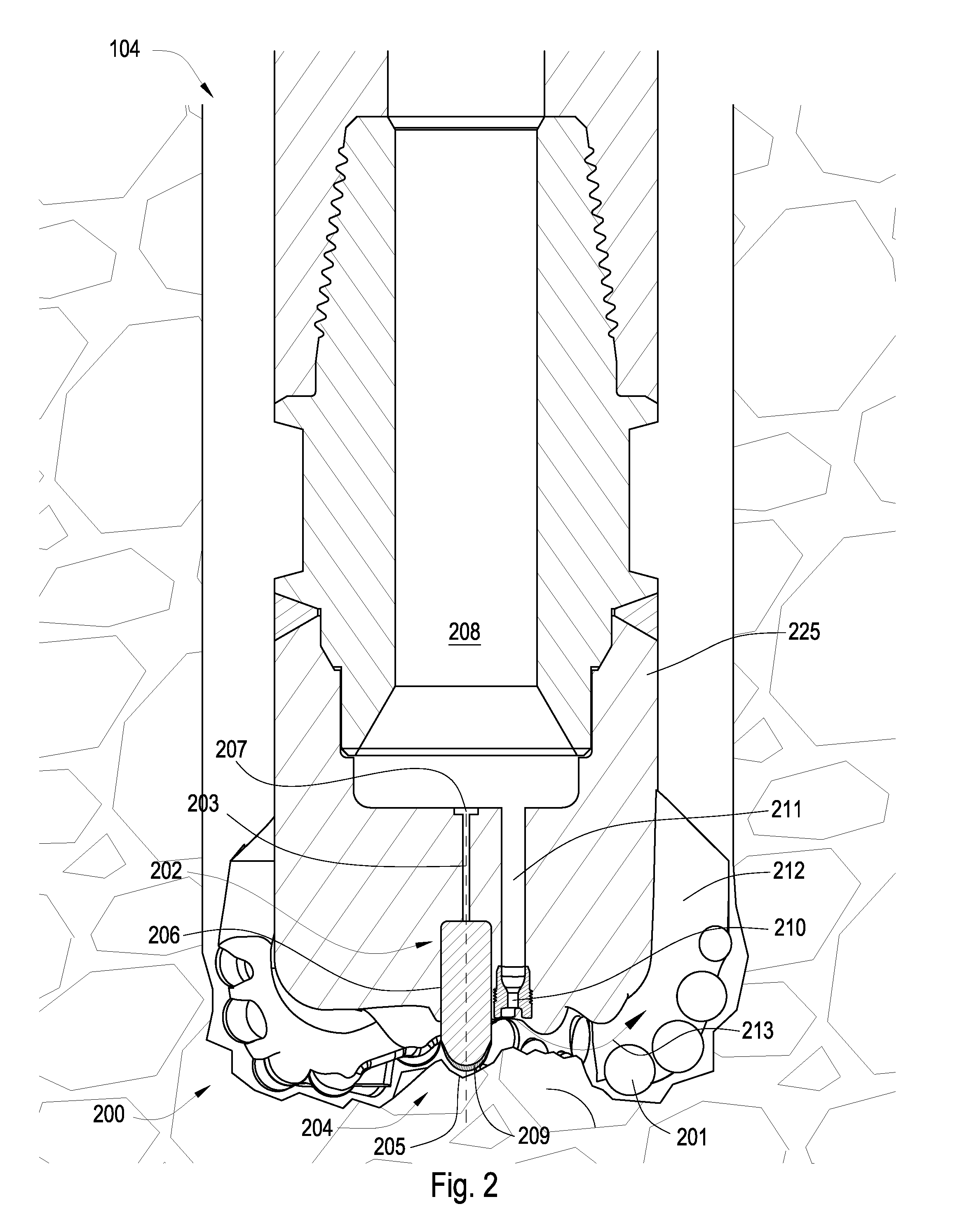
[0025]FIG. 1 is an embodiment of a drill string 100 suspended by a derrick 101. A bottom-hole assembly 102 is located at the bottom of a bore hole 103 and comprises a drill bit 104. As the drill bit 104 rotates downhole the drill string 100 advances farther into the earth. The drill string may penetrate soft or hard subterranean formations 105. The bottom-hole assembly 102 and / or downhole components may comprise data acquisition devices which may gather data. The data may be sent to the surface via a transmission system to a data swivel 106. The data swivel 106 may send the data to the surface equipment. Further, the surface equipment may send data and / or power to downhole tools and / or the bottom-hole assembly 102. A preferred data transmission system is disclosed in U.S. Pat. No. 6,670,880 to Hall, which is herein incorporated by reference for all that it discloses. However, in some embodiments, the no telemetry system is used. Mud pulse, short hop, or EM telemetry systems may also...


PUM


Abstract

A drill bit having a bit body, and axis of rotation, and a working face, the working face having a plurality of cutting elements. A jack element extends from the working face and is coaxial with the axis of rotation and is a hard metal insert. A plurality of high pressure jets are disposed within the working face and surround the jack element, wherein at least one jet is disposed at least as close to the jack element as an inner most cutting element of the plurality of cutting elements.

Description

[0001] This invention relates to drill bits, specifically drill bit assemblies for use in oil, gas and geothermal drilling. Often drill bits are subjected to harsh conditions when drilling below the earth's surface. Replacing damaged drill bits in the field is often costly and time consuming since the entire downhole tool string must typically be removed from the borehole before the drill bit can be reached. Bit balling in soft formations and bit whirl in hard formations may reduce penetration rates and may result in damage to the drill bit. Further, loading too much weight on the drill bit when drilling through a hard formation may exceed the bit's capabilities and also result in damage. Too often unexpected hard formations are encountered suddenly and damage to the drill bit occurs before the weight on the drill bit may be adjusted. [0002] The prior art has addressed bit whirl and weight on bit issues. Such issues have been addressed in the U.S. Pat. No. 6,443,249 to Beuershausen,...

Claims


Application Information

Patent Timeline
IPC IPC(8): E21B10/60
CPCE21B10/602
Inventor HALL, DAVID R.WILDE, TYSON J.
Owner SCHLUMBERGER TECH CORP
Learn More