
Automatically position adjustable wireless charger and charging method using the same

Inactive Publication Date: 2014-09-11
HANSHINKIJEON
View PDF2 Cites 15 Cited by
  • Summary
  • Abstract
  • Description
  • Claims
  • Application Information

AI Technical Summary

Benefits of technology

The present invention provides an automatically position adjustable wireless charger and a charging method using the same. The device allows for easier charging of portable terminals as the charging unit automatically aligns its power transmission coil and power reception coil, allowing for optimal electromagnetic induction. Additionally, the invention uses a hydraulic or gas cylinder method to move the power transmission unit, minimizing vibration and improving charging efficiency. Overall, the invention simplifies the charging process and provides improved convenience for users.

Problems solved by technology

However, when the contact terminals protrude to the outside, it is problematic in that the appearance of the product is not good, and the outside of the contact terminals is contaminated by foreign substances, thus causing a problem that a contact state may easily become bad.
Also, when a short circuit is generated at the battery due to a user's carelessness or the battery is exposed to moisture, charging energy may be easily destroyed.
In the past, the technology was limitedly applied only to an electric toothbrush, a radiotelephone for home use, a power tool and the like.
A smart phone enables a user to freely enjoy plentiful contents and multimedia at any time, but has a limit that the hours of use is short due to the restriction of a battery capacity.
However, according to the conventional art, it is problematic in that charging cannot be carried out when a position between a power transmission coil of the wireless charger and a power reception coil of a device to be charged is accurately fixed.

Method used


Image

  • Automatically position adjustable wireless charger and charging method using the same
  • Automatically position adjustable wireless charger and charging method using the same
  • Automatically position adjustable wireless charger and charging method using the same

Examples


Embodiment Construction

[0043]Hereinafter, preferred embodiments of the present invention will be described in detail with reference to the accompanying drawings. In the following description, it is to be noted that, when the functions of conventional elements and the detailed description of elements related with the present invention may make the gist of the present invention unclear, a detailed description of those elements will be omitted. Further, it should be understood that the shape and size of the elements shown in the drawings may be exaggeratedly drawn to provide an easily understood description of the structure of the present invention rather than reflecting the actual sizes of the corresponding elements.

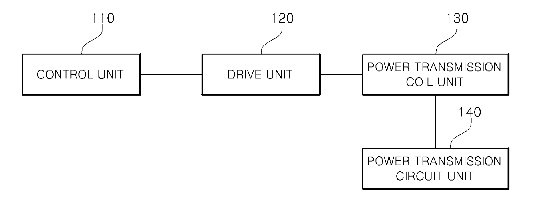
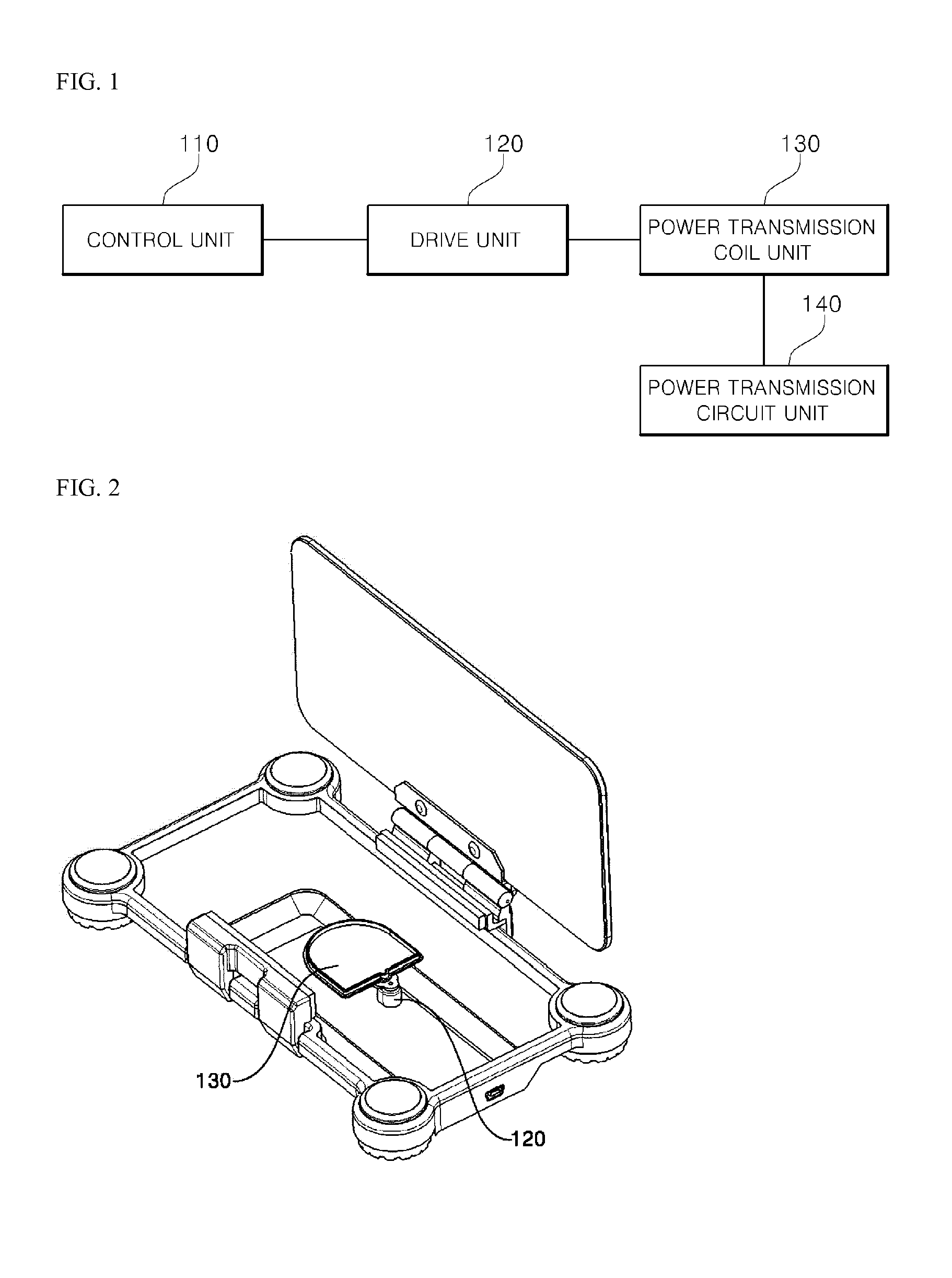
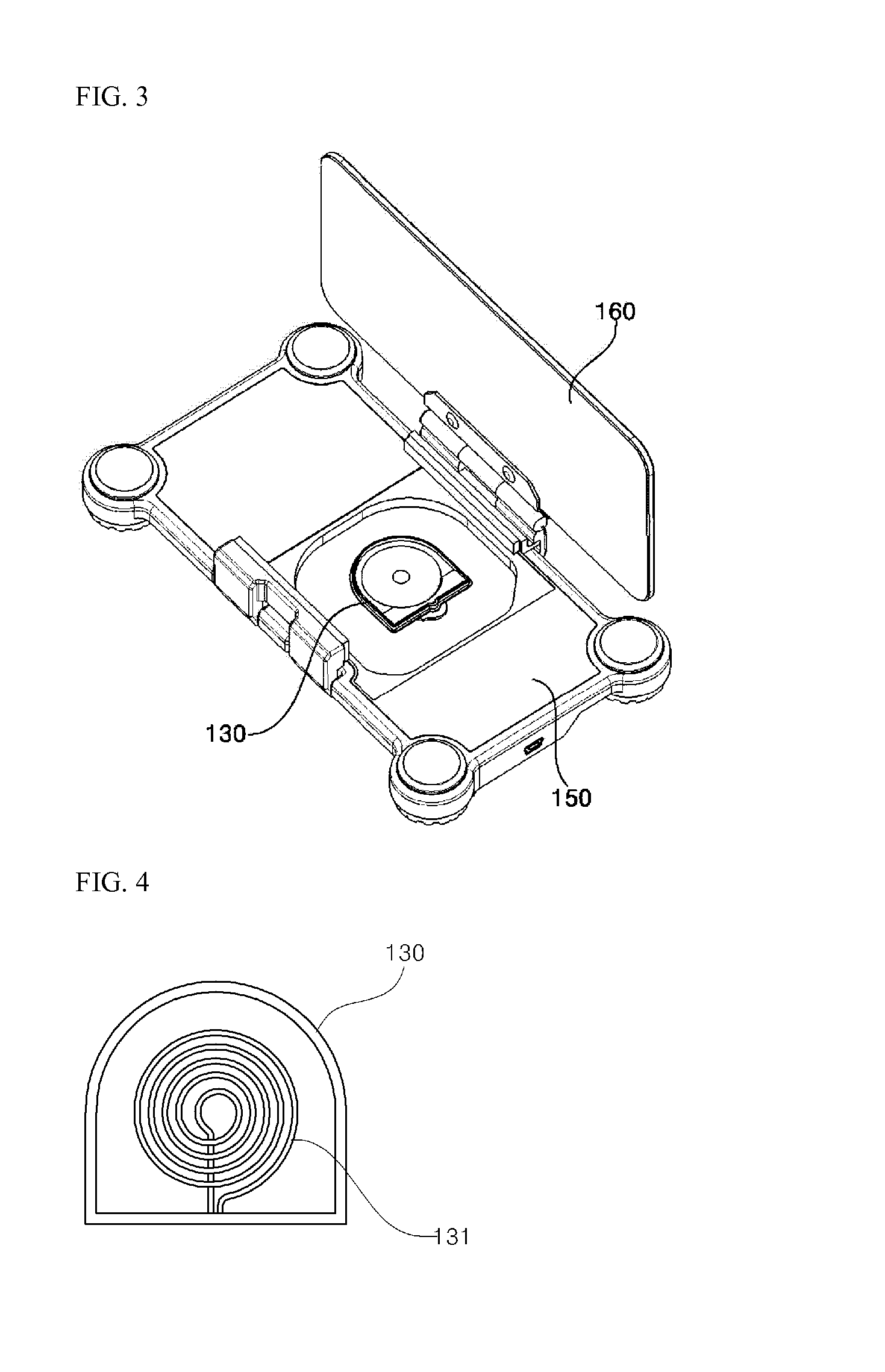
[0044]FIG. 1 is a block diagram showing an automatically position adjustable wireless charger according to one embodiment of the present invention, FIGS. 2 and 3 are perspective views illustrating the automatically position adjustable wireless charger according to one embodiment of the present i...


PUM


Abstract

Provided are an automatically position adjustable wireless charger and a charging method using the same, the wireless charger, including: a plurality of power transmission coil units having a power transmission coil for generating an induced current in a power reception coil of a portable terminal using electromagnetic induction; a power transmission circuit unit for supplying a current to the power transmission coil; a drive unit for moving a position of the power transmission coil unit; a power transmission unit for enabling the plurality of power coil units to be eccentrically rotated by transmitting power from the drive unit to the plurality of power coil units; and a control unit for stopping the drive unit and enabling the current to be supplied to the power transmission coil when a voltage applied to the power transmission coil is reduced by the power transmission coil being aligned at the power reception coil.

Description

CROSS-REFERENCE TO RELATED APPLICATION[0001]This application claims priority to Korean Patent Application No. 10-2013-0023705, filed on Mar. 6, 2013, No. 10-2013-0053354, filed on May 10, 2013, No. 10-2013-0106137, filed on Sep. 4, 2013, in the Korean Intellectual Property Office, the entire contents of each of which are hereby incorporated by reference.BACKGROUND OF THE INVENTION[0002]1. Field of the Invention[0003]The present invention relates to a wireless charger and a charging method using the same, more particularly, to an automatically position adjustable wireless charger and a charging method using the same, which has the improved convenience of charging.[0004]2. Description of the Related Arts[0005]In general, each of separate contact terminals is formed at the outside of each of a charging device and a battery, and the charging device and battery are electrically connected by connecting the two contact terminals to each other. However, when the contact terminals protrude t...

Claims


Application Information

Patent Timeline
IPC IPC(8): H02J7/02
CPCH02J7/025H02J7/0044H02J50/90H02J50/40H02J50/10
Inventor MOON, MYUNG-IL
Owner HANSHINKIJEON
Learn More