Manufacturing method for motor core
- Summary
- Abstract
- Description
- Claims
- Application Information
AI Technical Summary
Benefits of technology
Problems solved by technology
Method used
Image
Examples
Embodiment Construction
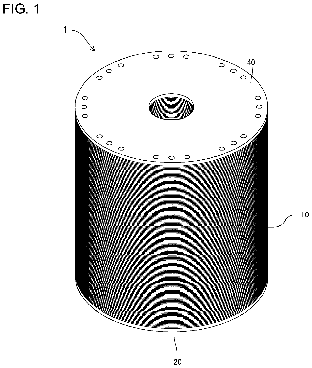
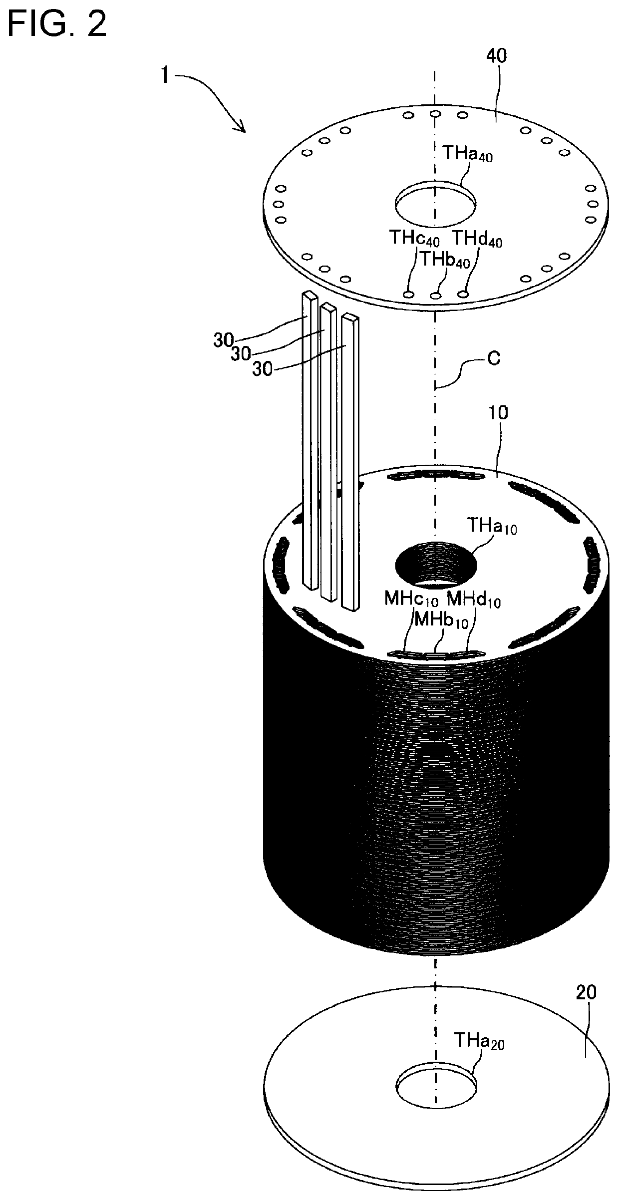
[0045]Hereinafter, a procedure for manufacturing a rotor core 1 shown in FIGS. 1 and 2 using a manufacturing method for a motor core according to an embodiment of the present disclosure will be described. The rotor core 1 is applied to a well-known rotor of an IPM motor. The rotor core 1 includes a stacked body 10, an end plate 20, a plurality of permanent magnets 30, and an end plate 40.
[0046](Stacked Body Manufacturing Step)
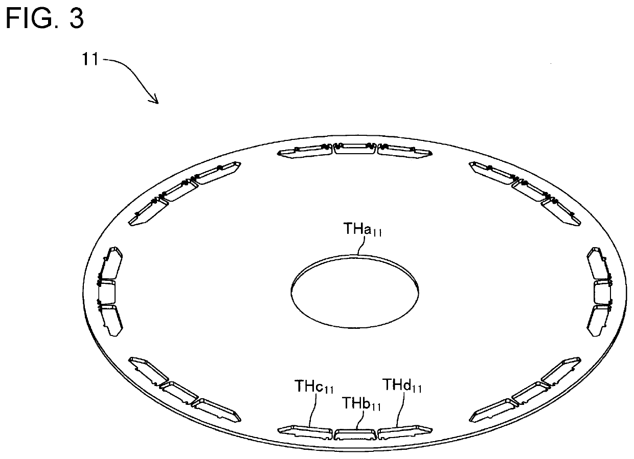
[0047]The stacked body 10 is formed by stacking iron core pieces 11 (see FIG. 3 and FIGS. 4A and 4B) each made of a silicon steel plate. The iron core piece 11 is formed by punching a base material. A circular through hole THa11 is provided in the central portion of the iron core piece 11. Through holes THb11, THc11, THd11 are provided in an outer peripheral edge portion of each of regions A obtained by dividing the iron core piece 11 into eight equal parts in the circumferential direction. The through holes THb11, THc11, THd11 are adjacent to each other in the...
PUM
 Abstract
Description
Claims
Application Information
 - R&D
- Intellectual Property
- Life Sciences
- Materials
- Tech Scout
- Unparalleled Data Quality
- Higher Quality Content
- 60% Fewer Hallucinations
Browse by: Latest US Patents, China's latest patents, Technical Efficacy Thesaurus, Application Domain, Technology Topic, Popular Technical Reports.
© 2025 PatSnap. All rights reserved.Legal|Privacy policy|Modern Slavery Act Transparency Statement|Sitemap|About US| Contact US: help@patsnap.com


