MRI coil assembly with a radio frequency shield switchable between a blocking state and a transparent state

Active Publication Date: 2014-09-11
KONINKLIJKE PHILIPS ELECTRONICS NV
View PDF1 Cites 16 Cited by
  • Summary
  • Abstract
  • Description
  • Claims
  • Application Information

AI Technical Summary

Benefits of technology

[0033]In another embodiment the coil assembly has a second surface configured for receiving a portion of the subject. The second surface is directed away from the imaging zone. The radio-frequency shield is between the second surface and that at least one coil element. The coil assembly has at least two outer surfaces. One surface is directed towards the imaging zone and one is directed away from it. Portions of the subject in contact or in the direction of the second surface will be shielded from radio-frequency energy generated by the coil assembly. This may help to reduce the radio-frequency heating in portions of the subject which are s

Problems solved by technology

A disadvantage of current multichannel systems is that there may be

Method used


Image

  • MRI coil assembly with a radio frequency shield switchable between a blocking state and a transparent state
  • MRI coil assembly with a radio frequency shield switchable between a blocking state and a transparent state
  • MRI coil assembly with a radio frequency shield switchable between a blocking state and a transparent state

Examples


Example

[0078]Like numbered elements in these figures are either equivalent elements or perform the same function. Elements which have been discussed previously will not necessarily be discussed in later figures if the function is equivalent.

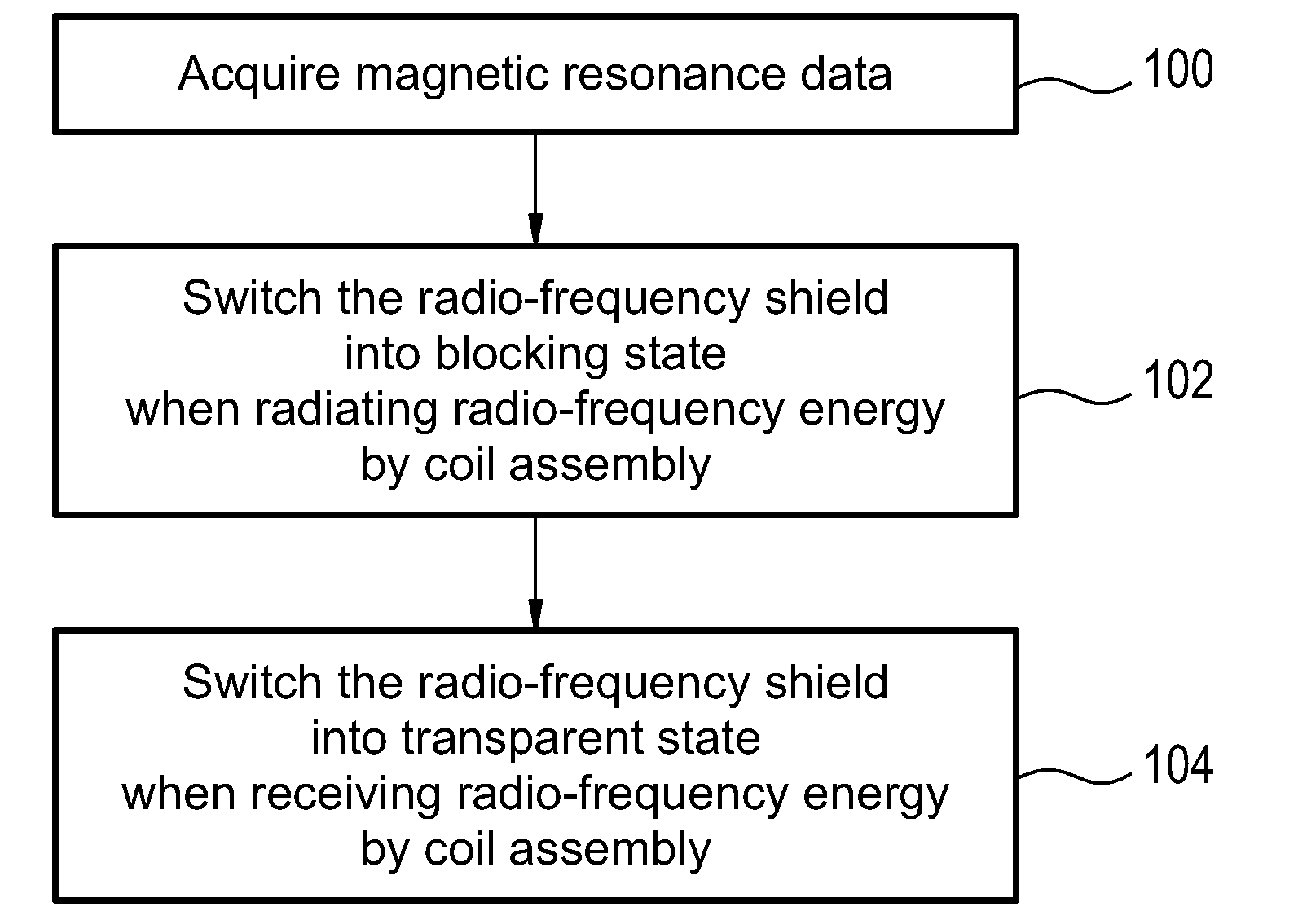
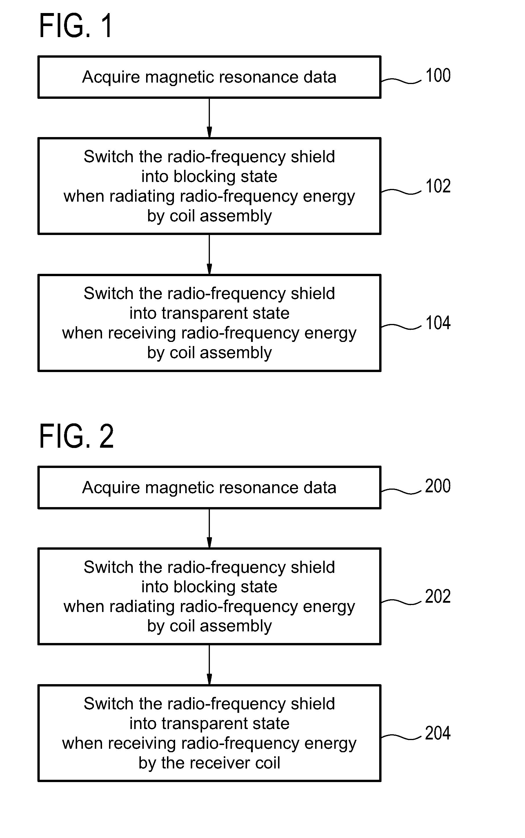
[0079]FIG. 1 shows a flow diagram which illustrates a method according to an embodiment of the invention. In step 100 magnetic resonance data is acquired. In step 102 the radio-frequency shield is switched into the blocking state when eradiating radio-frequency energy by the coil assembly. In step 104 the radio-frequency shield is switched into the transparent state when receiving the radio-frequency energy by the coil assembly. It should be noted that steps 102 and 104 may each be performed multiple times during the acquisition of magnetic resonance data 100.

[0080]FIG. 2 shows a flow diagram which illustrates a further embodiment of a method according to the invention. In step 200 magnetic resonance data is acquired. In step 202 the radio-frequency shi...


PUM


Abstract

The invention provides for a magnetic resonance imaging system (300, 400) for acquiring magnetic resonance data (342). The magnetic resonance imaging system comprises a coil assembly (319) configured for radiating and/or receiving radio frequency energy from an imaging zone. The coil assembly has a first surface (315) configured for being directed towards the imaging zone and comprises at least one coil element (317). The coil assembly further comprises a radio frequency shield (319) switchable between an RF blocking state (804) and an RF transparent state (802). The at least one coil element is between the first surface and the radio frequency shield. The switchable radio frequency shield comprises at least two conductive elements (322). The radio frequency shield comprises at least one radio frequency switch (324) configured for electrically connecting the at least two conductive elements in the blocking state and disconnecting the at least two conductive elements in the transparent state.

Description

TECHNICAL FIELD[0001]The invention relates to magnetic resonance imaging, in particular to a coil assembly with a switchable radio frequency shield.BACKGROUND OF THE INVENTION[0002]A magnetic field is used in Magnetic Resonance (MR) Imaging to align the nuclear spins of atoms as part of the procedure for producing images within the body of a patient. This magnetic field is referred to as the B0 field. During an MR scan, Radio Frequency (RF) pulses generated by a transmitter or amplifier and an antenna cause perturbations to the local magnetic field and can be used to manipulate the orientation of the nuclear spins relative to the B0 field. Radio Frequency (RF) signals emitted by the nuclear spins are detected by a receiver coil, and these RF signals are used to construct the MRI images.[0003]In most MR-systems to date a volume coil (e.g. quadrature body coil, QBC) is used to transmit the high power signals for spin excitation. For whole body imaging this is the standard setup for up...

Claims


Application Information

Patent Timeline
IPC IPC(8): G01R33/421
CPCG01R33/4215G01R33/3415G01R33/3635G01R33/422G01R33/481
Inventor LEUSSLER, CHRISTOPHWIRTZ, DANIEL
Owner KONINKLIJKE PHILIPS ELECTRONICS NV
Why Eureka
Try Eureka