
Transmission system, transmission apparatus, and transmission method

a transmission system and transmission apparatus technology, applied in the field of transmission systems, can solve problems such as preventing proper path construction, and achieve the effect of high reliability

Inactive Publication Date: 2014-09-11
HITACHI LTD
View PDF2 Cites 156 Cited by
  • Summary
  • Abstract
  • Description
  • Claims
  • Application Information

AI Technical Summary

Benefits of technology

The invention provides a communication system that is highly reliable and can connect traditional MPLS and MPLS-TP networks through a network control apparatus. It separates network control processing from data transmission along a path, preventing processing errors in the network control apparatus from affecting path continuity. This ensures that data can be transmitted securely and without interruption.

Problems solved by technology

When a communication network using traditional MPLS (IP / MPLS) and a communication network using MPLS-TP are connected, the difference in path building method between the two communication networks prevents proper building of a path that connects the IP / MPLS communication network and the MPLS-TP communication network.
However, when a path is built through cooperation between the IP layer protocol for building a path for the IP / MPLS communication network and the network control apparatus for building a path for the MPLS-TP communication network, an error of IP layer protocol processing in the network control apparatus which should not be treated as that of path continuity is treated as an error of path continuity in the IP / MPLS communication network where the MPLS-TP network is connected through the path.

Method used


Image

  • Transmission system, transmission apparatus, and transmission method
  • Transmission system, transmission apparatus, and transmission method
  • Transmission system, transmission apparatus, and transmission method

Examples


Embodiment Construction

[0029]An embodiment of this invention is described in detail below with reference to the drawings. Components that are substantially the same are denoted by the same reference symbol in order to avoid repetitive descriptions.

[0030]The embodiment of this invention is described with reference to FIGS. 1 to 13.

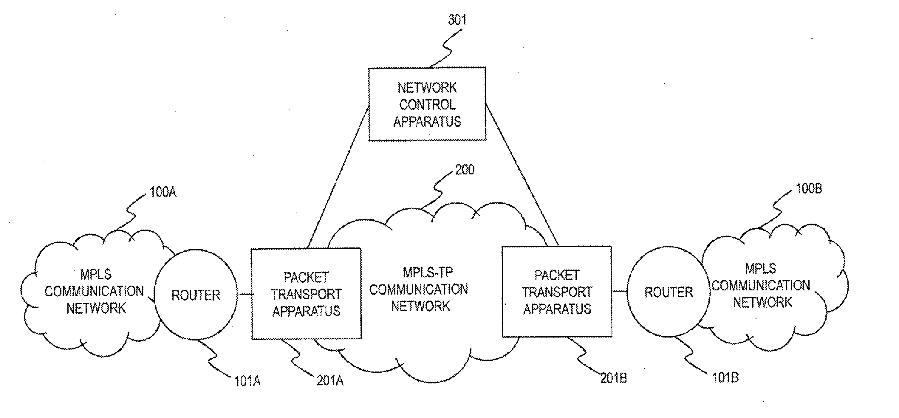
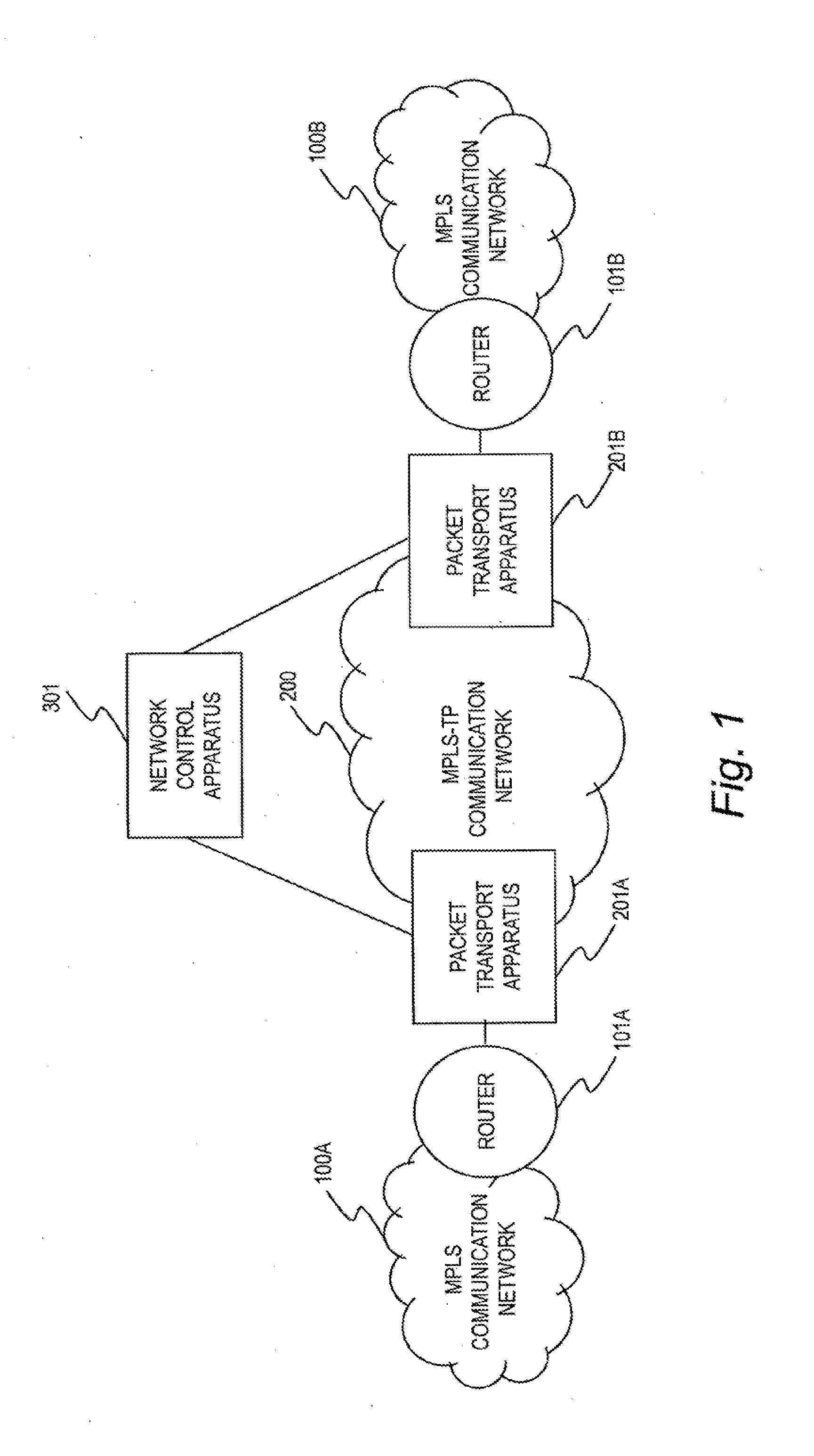
[0031]FIG. 1 is an explanatory diagram of a communication system according to the embodiment of this invention.

[0032]The communication system of this embodiment includes routers (transfer apparatus) 101A and 101B (hereinafter collectively referred to as routers 101), packet transport apparatus (transport apparatus) 201A and 201B (hereinafter collectively referred to as packet transport apparatus 201), and a network control apparatus 301 (control apparatus), which controls the packet transport apparatus 201. The routers 101 are used to construct MPLS communication networks (transfer networks) 100A and 100B (hereinafter collectively referred to as MPLS communication networks 100), ...


PUM


Abstract

A transport system comprises a transport apparatus, which is used to construct a transport network using MPLS-TP; and a control apparatus for establishing a path in the transport network. The transport apparatus is coupled to a transfer apparatus, which is used to construct a transfer network using a network protocol different from an MPLS-TP protocol and uses the network protocol to establish a path in the transfer network in an autonomous distributed manner. The control apparatus and the transfer apparatus use the network protocol of the transfer network to transmit / receive, via the transport apparatus, control messages for controlling the transfer network. The transport apparatus avoids notifying the transfer apparatus of the fact that the control apparatus is not in a normal state, in a case where the path established in the transport network is determined as the normal state, even the control apparatus is determined as the abnormal state.

Description

CLAIM OF PRIORITY[0001]The present application claims priority from Japanese patent application JP 2013-48098 filed on Mar. 11, 2013, the content of which is hereby incorporated by reference into this application.BACKGROUND OF THE INVENTION[0002]This invention relates to a transport system including transport apparatus, which is used to construct a transport network using MPLS-TP, and a control apparatus for controlling the transport apparatus.[0003]Internet Protocol (IP) and Multiprotocol Label Switching (MPLS) are known as technologies for data communication between communication apparatus, which are used to construct an IT network.[0004]IP is a technology that uses IP address for data communication between communication apparatus. Details of IP are defined in Internet Engineering Task Force (IETF) Request for Comments (RFC) 791 (see J. Postel, “IETF RFC 791 Internet Protocol”, September 1981) and IETF RFC 2460 (see S. Deering, et al., “IETF RFC 2460 Internet Protocol, Version 6 (...

Claims


Application Information

Patent Timeline
IPC IPC(8): H04L12/723H04L45/50H04L45/28
CPCH04L45/50H04L45/28
Inventor SHIBATA, TAKESHITAKAHASHI, KIYOTAKAKIMURA, MASAHIRO
Owner HITACHI LTD
Learn More