
System and Method for Detecting Sheathing and Unsheathing of Localization Elements

a technology of localization elements and detection systems, applied in the field of localization systems, can solve the problems of non-linear and erratic voltage gradients in the vicinity of localization electrodes within the sheath, difficult for the localization system to accurately and precisely render an image of the medical device for the practitioner, and unreliable impedance measurements, etc., to reduce the burden on the practitioner, less reliable, and less reliable.

Active Publication Date: 2014-09-11
ST JUDE MEDICAL CARDILOGY DIV INC
View PDF1 Cites 56 Cited by
  • Summary
  • Abstract
  • Description
  • Claims
  • Application Information

AI Technical Summary

Benefits of technology

This patent describes a new system for detecting changes in the location of a medical device, called a localization element, which can help healthcare professionals better understand and treat certain medical conditions. The system also alerts the practitioner when the localization element is not in its usual place, which can make it less reliable to obtain accurate measurements. By analyzing data collected by the localization element, the system can discard data collected during a medical study and make the results less reliable. Overall, the invention makes it easier for medical professionals to detect and account for changes in the location of a medical device, which can improve the accuracy and safety of medical procedures.

Problems solved by technology

One drawback of an impedance-based system, however, is that the impedance measurements become unreliable when the medical device is withdrawn into the introducer.
This is because the introducer is normally made of an insulating material, such that the voltage gradient in the vicinity of localization electrodes within the sheath becomes non-linear and erratic.
Indeed, a localization electrode within a sheath may appear to wander widely, making it difficult for the localization system to accurately and precisely render an image of the medical device for the practitioner.
Although visual recognition of this condition is possible, there is no extant system or method to do so analytically.

Method used


Image

  • System and Method for Detecting Sheathing and Unsheathing of Localization Elements
  • System and Method for Detecting Sheathing and Unsheathing of Localization Elements
  • System and Method for Detecting Sheathing and Unsheathing of Localization Elements

Examples


Embodiment Construction

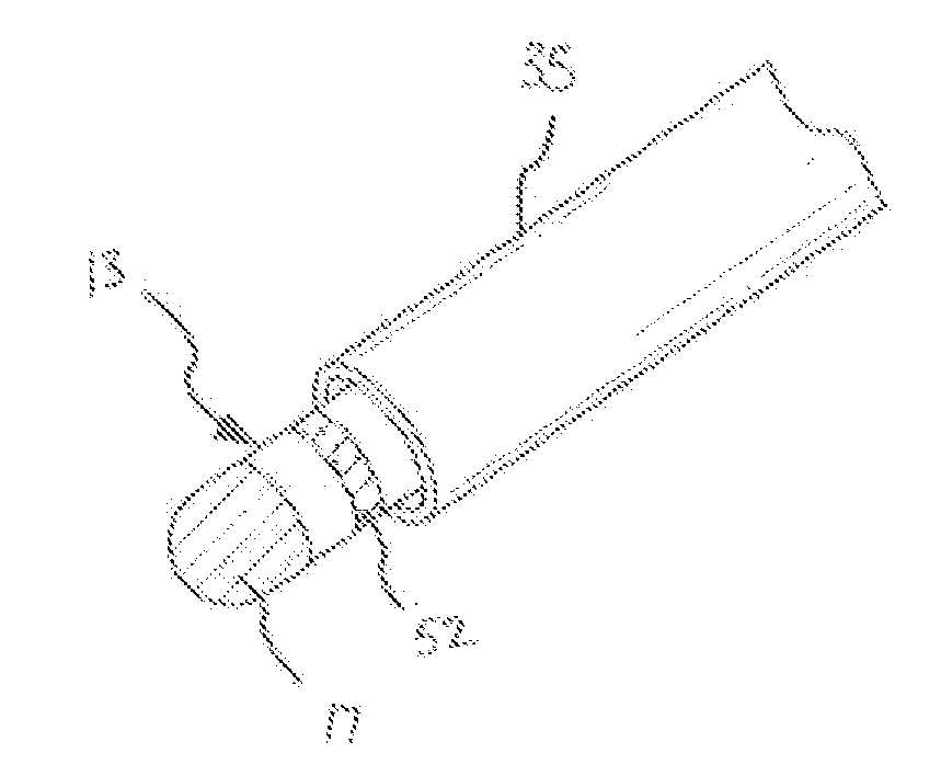
[0029]The present invention provides methods, apparatuses and systems for detecting when a localization element, such as a localization electrode, emerges from and / or is withdrawn into another device such as an introducer sheath (referred to herein as a “localization element / sheath state change”). For purposes of illustration, embodiments of the invention will be described in detail herein in the context of a localization system utilized in a cardiac electrophysiology procedure. It is contemplated, however, that the present invention may be practiced to good advantage in other contexts.

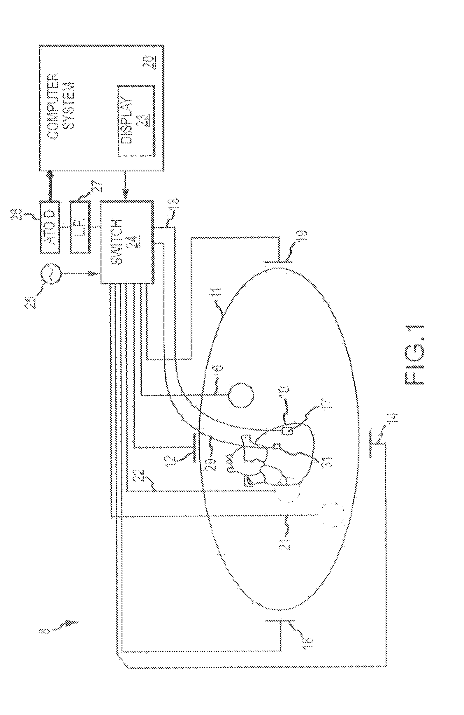
[0030]FIG. 1 shows a schematic diagram of a localization system 8 for conducting cardiac electrophysiology studies by navigating a cardiac catheter and measuring electrical activity occurring in a heart 10 of a patient 11 and three-dimensionally mapping the electrical activity and / or information related to or representative of the electrical activity so measured. System 8 can be used, for example, to ...


PUM


Abstract

A method of detecting whether a localization element is within or outside of an introducer sheath generally includes obtaining a localization signal from the localization element and detecting the state of the localization element relative to the sheath based upon the quadrature component of the localization signal. A baseline quadrature component is typically established with the localization element outside of the sheath. When the quadrature component deviates from this baseline value, it is indicative of the localization element being within the sheath. Conversely, when the quadrature component remains relatively close to the baseline value, it is indicative of the localization element being outside of the sheath. In an electrophysiology study, the state information can be used to take corrective action with respect to the data being collected.

Description

BACKGROUND[0001]a. Field of the Invention[0002]The instant disclosure relates to localization systems, such as those used in cardiac diagnostic and therapeutic procedures. In particular, the instant disclosure relates to systems, apparatuses and methods for detecting when a localization element(s), such as an electrode(s), emerges from and / or is retracted into an introducer sheath or other enveloping instrument.[0003]b. Background Art[0004]Catheters are used for an ever-growing number of procedures. For example, catheters are used for diagnostic, therapeutic, and ablative procedures, to name just a few examples. Typically, the catheter is manipulated through the patient's vasculature and to the intended site, for example, a site within the patient's heart. In many instances, the catheters are inserted into the body and navigated to the target location with the aid of an introducer sheath (sometimes referred to as simply an “introducer” or a “sheath”). As the ordinarily skilled artis...

Claims


Application Information

Patent Timeline
Patent Type & Authority Applications(United States)
IPC IPC(8): A61B5/042A61B5/296
CPCA61B5/042A61B5/063A61B5/287A61B5/6852A61B5/6885A61B5/746
Inventor CURRAN, TIMOTHY G.HILL, ANTHONY D.
Owner ST JUDE MEDICAL CARDILOGY DIV INC
Learn More