Gas-to-Liquid Heat Exchange System with Multiple Liquid Flow Patterns

a heat exchange system and liquid flow pattern technology, applied in lighting and heating apparatus, automatic control of ignition, water feed, etc., can solve the problems of not being able to provide extra heat, not enough of it at the power plant, and its price has also been dramatically reduced

Active Publication Date: 2014-09-18
NOOTER ERIKSEN INC
View PDF3 Cites 8 Cited by
  • Summary
  • Abstract
  • Description
  • Claims
  • Application Information

AI Technical Summary

Benefits of technology

[0040]In an embodiment of the system, after the feedwater has passed through either the first configuration or the second configuration, the feedwater is passed to a low pressure evaporator.

Problems solved by technology

Its price has also been falling dramatically in recent years as new drilling techniques such as hydraulic fracturing (or fracking) have opened up previously unavailable deposits.
As sulfuric acid is highly corrosive to the material of tubes (200), such formation can cause damage to tubes (200), eventually requiring a shutdown and repair of the HRSG (100) with all associated costs.
While natural gas is always a preferred fuel, sometimes there is simply not enough of it available at the power plant.
However, for designs such as those of FIG. 2 and FIG. 3 that utilize an external heat exchanger, the system is often not capable of providing extra heat to the feedwater (407) to raise it substantially above 140° F. because of the use of different fuel and, thus, sulfuric acid can condense on the cold end tubes of the tube bank (200) designed for the 140° F. input feedwater (407) which would no longer be of sufficient temperature to prevent condensation and a full bypass of all section of the economizer (205) would be required to prevent tube bank (200) corrosion.

Method used


Image

  • Gas-to-Liquid Heat Exchange System with Multiple Liquid Flow Patterns
  • Gas-to-Liquid Heat Exchange System with Multiple Liquid Flow Patterns
  • Gas-to-Liquid Heat Exchange System with Multiple Liquid Flow Patterns

Examples


Embodiment Construction

)

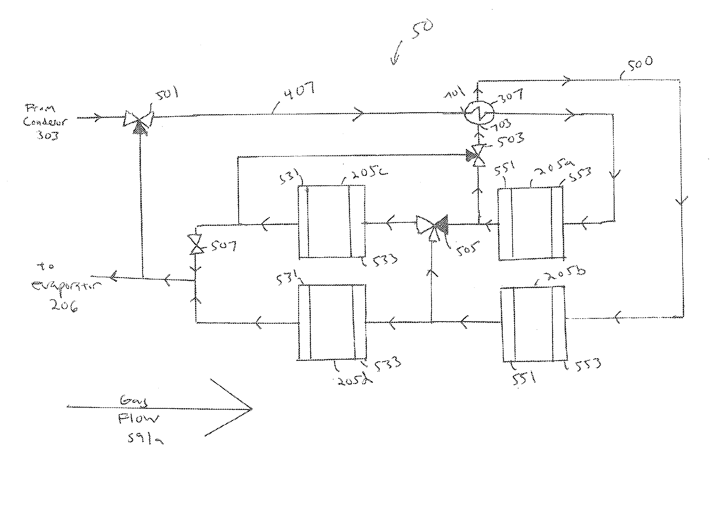
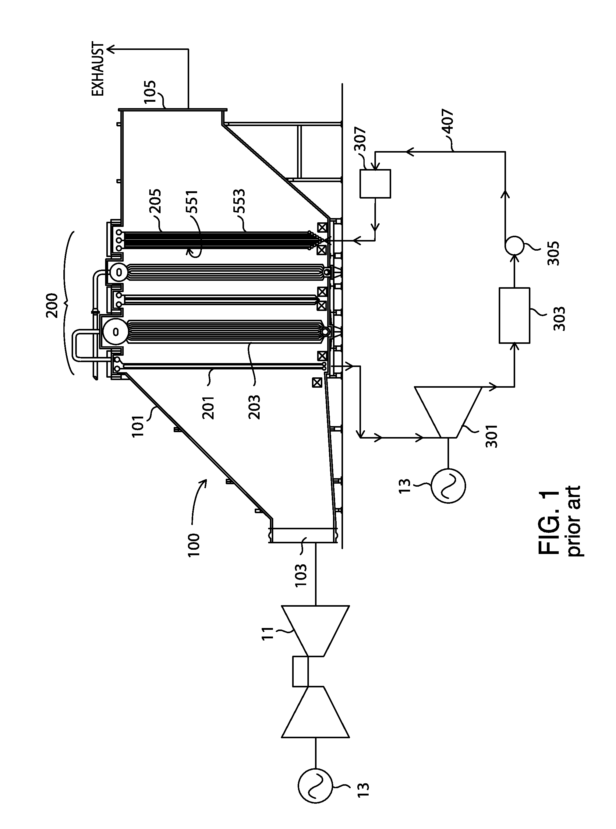
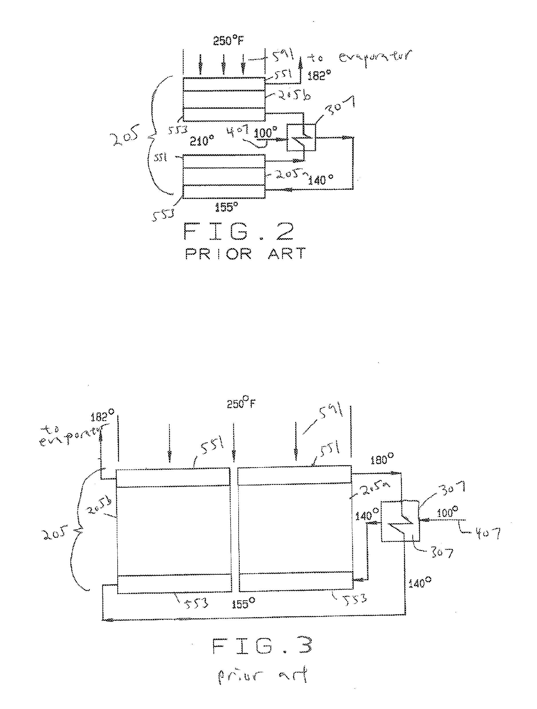
[0069]This disclosure will discuss systems and methods for the design of a heat recovery steam generator (HRSG) (100) which utilizes an external liquid-to-liquid heat exchanger (307) for preheating condensate (407) and that allows for a variable water flow pattern to alter the temperature that the condensate (407) enters tube banks (200) within the duct (101) based on the gas composition from which the HRSG (100) is recovering heat. Thus, the input temperature of the condensate (407) is variable and the temperature can be selected by altering the chosen pathway.

[0070]It should be recognized that, while this disclosure will specifically describe the piping arrangement (500) of an economizer (205) in conjunction with an HRSG (100) designed primarily for capturing heat from natural gas exhaust (591a), the piping arrangement (500) and methodology is equally suitable for HRSGs (100) used for other primary forms of gas-to-liquid heat exchange, and other systems for capturing heat from he...


PUM


Abstract

Systems and methods for the design of a heat recovery steam generator (HRSG) or similar system that is designed to extract heat from hot gases flowing through a duct which utilizes an external liquid-to-liquid heat exchanger for preheating feedwater. The systems and methods allow for multiple water flow patterns to adjust the temperature of the feedwater into the gas duct.

Description

BACKGROUND[0001]1. Field of the Invention[0002]This invention generally relates to gas-to-liquid heat exchange systems and more particularly to a system allowing multiple liquid paths to provide different temperatures of feed liquid entering the system.[0003]2. Description of the Related Art[0004]Natural gas represents a significant source of electrical energy in the United States and other countries. It burns with few emissions and is available throughout much of the world. Its price has also been falling dramatically in recent years as new drilling techniques such as hydraulic fracturing (or fracking) have opened up previously unavailable deposits. Power plants which convert natural gas into electrical energy are efficient and, in comparison to hydroelectric projects and coal-fired plants, are relatively easy and inexpensive to construct.[0005]In the typical plant as shown in FIG. 1, the natural gas burns in a gas turbine (11), causing the rotor of the turbine (11) to revolve and ...

Claims


Application Information

Patent Timeline
Patent Type & Authority Applications(United States)
IPC IPC(8): F01K23/10F22D1/02
CPCF22D1/02F01K23/101F22B1/1815F22B35/007Y02E20/16F22B37/025F22D1/003F22D5/34F01K23/10F02C6/18F22D1/00
Inventor RECHTMAN, YURI
Owner NOOTER ERIKSEN INC
Why Eureka
Try Eureka