
Drawing method and servo press system

a servo press and drawing method technology, applied in forging presses, forging/pressing/hammering machines, forging/pressing/hammering apparatuses, etc., can solve the problems of inability to achieve energy saving and large amount of kinetic energy, and achieve the effect of reducing the press load, lowering the sub slide, and reducing the drive energy

Active Publication Date: 2014-09-18
AIDA ENG LTD
View PDF5 Cites 9 Cited by
  • Summary
  • Abstract
  • Description
  • Claims
  • Application Information

AI Technical Summary

Benefits of technology

This patent describes a method to improve the process of drawing a blank piece of metal by reducing the resistance of sliding against another material. The method involves stopping the movement of a servo motor for a short period of time and then increasing the force applied to the metal piece being drawn. This reduces the load on the motor and increases efficiency, resulting in a temporary improvement in the motor's performance. The method also allows for energy savings and faster press cycles.

Problems solved by technology

The invention described in Japanese Patent Application Laid-Open No. 11-254197 has a problem that a large amount of kinetic energy is consumed for driving the servo press itself (energy saving cannot be achieved) since the slide is repetitively raised and lowered during the forming operation.

Method used


Image

  • Drawing method and servo press system
  • Drawing method and servo press system
  • Drawing method and servo press system

Examples


first embodiment

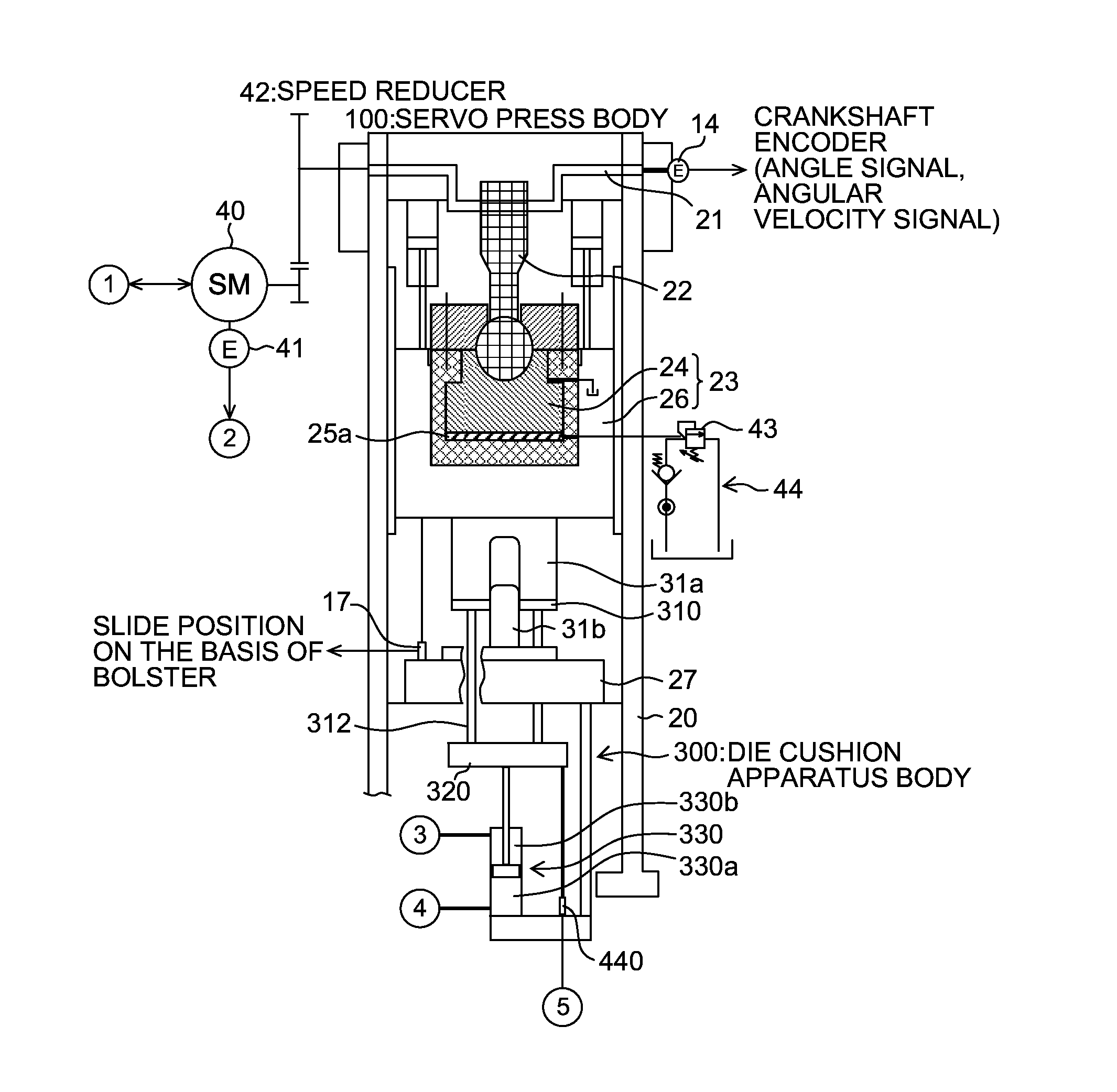
[0083]FIGS. 4 and 5 are system configuration diagrams illustrating a first embodiment of a servo press system according to the present invention.

[0084]As shown in FIGS. 4 and 5, the servo press system according to the first embodiment mainly includes a servo press (a servo press body 100 and a servo press control apparatus 200), a die cushion apparatus (a die cushion apparatus body 300 and a die cushion control apparatus 400), and an energy protection control apparatus 500. Although the energy protection control apparatus 500 is independent, the energy protection control apparatus 500 may also be included in the servo press control apparatus 200 or the die cushion control apparatus 400.

[0085]As shown in FIG. 4, the servo press body 100 is a crank-type servo press including a column (frame) 20, a crankshaft 21, a connecting rod 22, a slide 23 (a main slide 24 and a sub slide 26), and a bolster 27.

[0086]The main slide 24 is guided so as to be able to reciprocate in a straight directio...

second embodiment

[0138]FIGS. 8 and 9 are system configuration diagrams illustrating a second embodiment of the servo press system according to the present invention.

[0139]As shown in FIGS. 8 and 9, the servo press system according to the second embodiment mainly includes the servo press (the servo press body 100, the servo press control apparatus 200, and a sub slide control apparatus 600), the die cushion apparatus (the die cushion apparatus body 300 and the die cushion control apparatus 400), and an energy protection control apparatus 500A. Portions common to those in the first embodiment shown in FIGS. 4 and 5 are assigned the same reference numerals, and the detailed description thereof is omitted.

[0140]As shown in FIGS. 8 and 9, the servo press according to the second embodiment differs from the servo press according to the first embodiment in that a sub slide drive device 50 is provided instead of the overload removal device 44 of the servo press in the first embodiment, and the sub slide cont...


PUM

PropertyMeasurementUnit
die cushion forceaaaaaaaaaa
heightaaaaaaaaaa
storage energyaaaaaaaaaa

Abstract

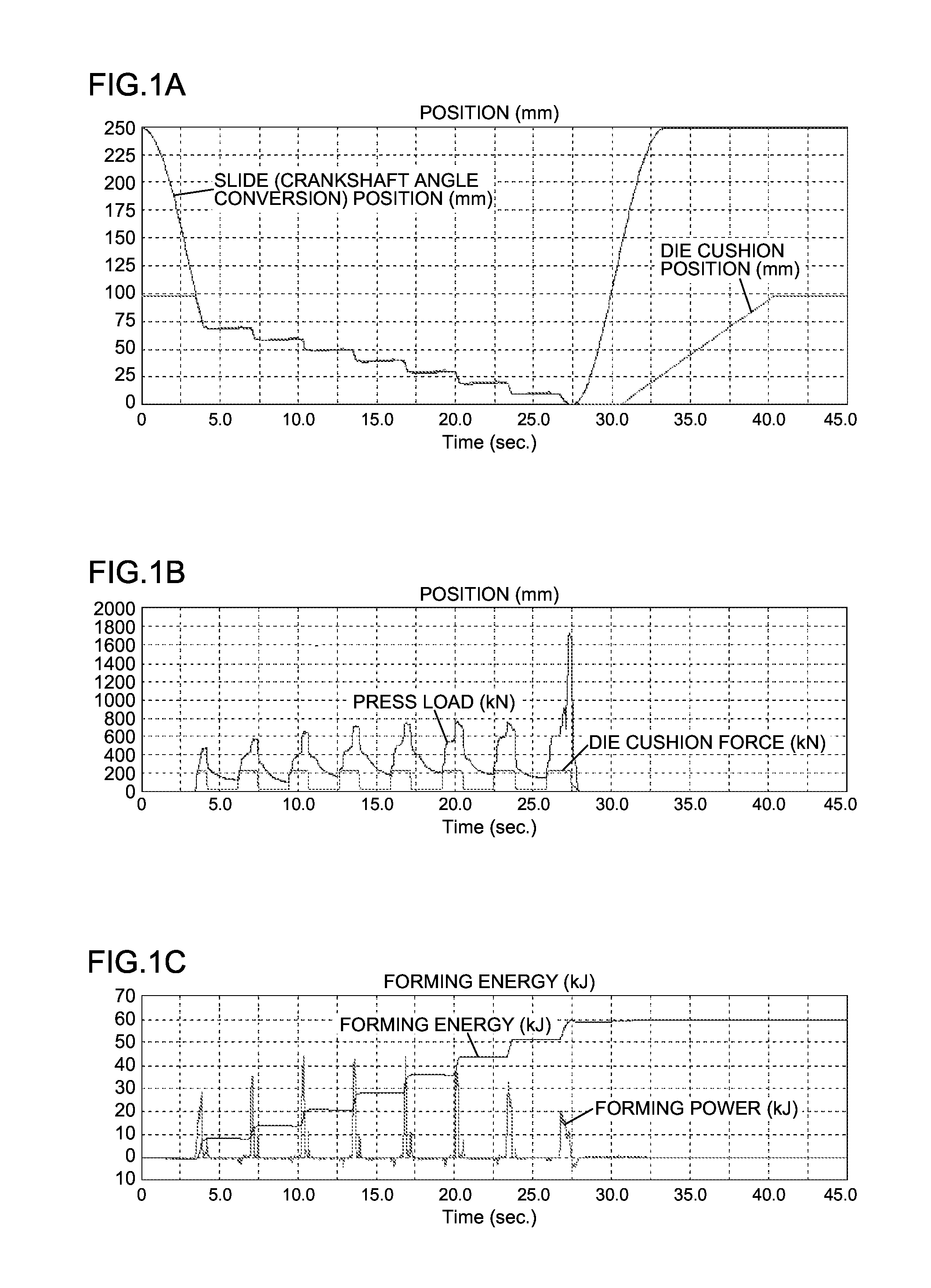
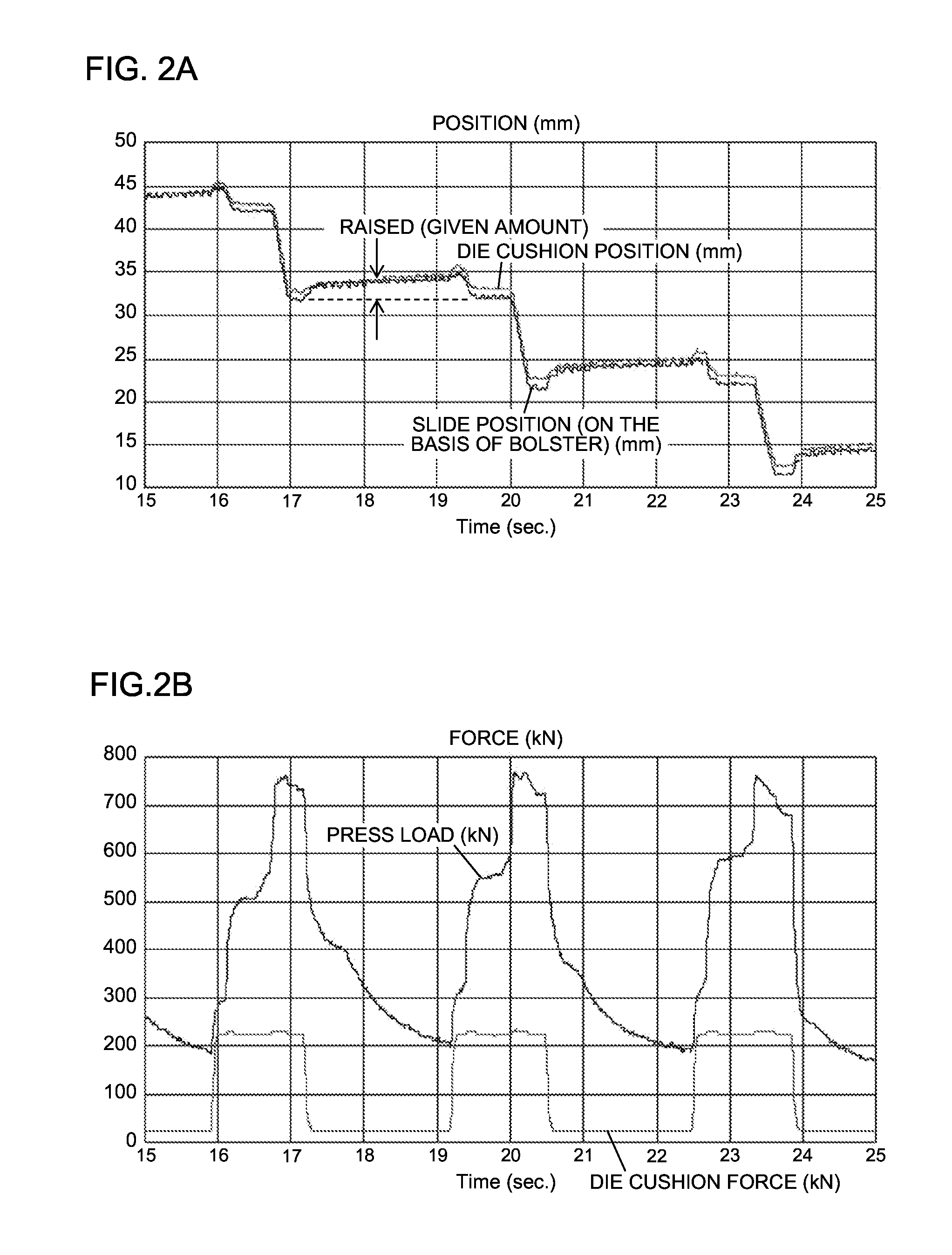
The present invention provides a servo press system and a drawing method using the servo press system. The drawing method according to the aspect of the present invention includes: a stopping step of stopping the slide for a first period in a course of a stroke for performing drawing; a keeping step of reducing the die cushion force to below a predetermined die cushion force and keeping the die cushion force for a second period within the first period for which the slide is stopped; and a restarting step of restarting the slide after keeping the die cushion force for the second period, wherein drawing including the stopping step, the keeping step, and the restarting step is performed at least one time in the course of the stroke for performing drawing.

Description

BACKGROUND OF THE INVENTION[0001]1. Field of the Invention[0002]The present invention relates to a drawing method and a servo press system, and more particularly, to a technique for deep drawing a material by use of a servo press which transmits a drive force to a slide from a servo motor via a link mechanism.[0003]2. Description of the Related Art[0004]There has been conventionally proposed an automatic slide position control apparatus for a servo press which enables a servo press with relatively small forming energy to perform forming that requires large energy (Japanese Patent Application Laid-Open No. 11-254197).[0005]The automatic slide position control apparatus for a servo press lowers a slide at a set load, returns (raises) the slide by a given dimension when the slide stops with the forming changed from a dynamic friction to a static friction, and thereafter re-pressurizes the slide to advance the forming with a dynamic friction. By repeating the up-and-down operation of lo...

Claims


Application Information

Patent Timeline
Patent Type & Authority Applications(United States)
IPC IPC(8): B21D43/05B21D22/20
CPCB21D22/20B21D43/05B21D24/02B21D24/00
Inventor KOHNO, YASUYUKIKONDO, TADAHIROIWAMURA, RYOSHO
Owner AIDA ENG LTD
Learn More