Metal element for continuously variable transmission and method of manufacture the same

a technology of metal elements and transmission lines, applied in the direction of manufacturing tools, gearing, shaping tools, etc., can solve the problems of excessive polishing, small large thickness of locking edges, so as to reduce transmitting the driving force. , the effect of reducing the pressing load for shaping the projection section

Active Publication Date: 2019-10-03
HONDA MOTOR CO LTD
View PDF0 Cites 3 Cited by
  • Summary
  • Abstract
  • Description
  • Claims
  • Application Information

AI Technical Summary

Benefits of technology

[0014]According to a first aspect of the present disclosure, the metal element, which is pressed and punched by a mold, includes: the neck section positioned between a pair of right and left ring slots; the ear section continuous to a radially outer side of the neck section; and the body section continuous to a radially inner side of the neck section, and the locking edge extending in a right-left direction is formed at a radially outer end of a front surface of the body section. Since the metal element includes a projection section extending in the right-left direction on the back surface of the body section at a position backward of the locking edge, the locking edge of the front surface of the metal element on the back side comes into contact with the projection section of the back surface of the metal element on the front side, and thus the height of the projection section compensates for the insufficiency of the thickness of the locking edge relative to the thickness of the ear section, and it is possible to appropriately maintain the contact relationship between adjacent metal elements.
[0015]According to a second aspect of the present disclosure, the position of the radially outer end of the projection section substantially coincides with the radial position of the locking edge. Thus, the locking edge of the metal element 23 on the back side is brought into contact with the projection section of the metal element on the front side, and it is possible to effectively transmit the driving force.
[0016]According to a third aspect of the present disclosure, the metal element includes a depressed section on the radially inner side of the projection section. Thus, the depressed section makes it possible to ensure the space into which the material flows, and to reduce the pressing load for shaping the projection section.
[0017]According to a fourth aspect of the present disclosure, the mold includes a main punch which comes into contact with the back surface of the metal element, and a counter punch which comes into contact with the front surface of the metal element, and the main punch has a depressed section that shape the projection section. Thus, it is possible to form the projection section of the back surface of the body section easily.
[0018]According to a fifth aspect of the present disclosure, the mold includes a main punch which comes into contact with the back surface of the metal element, and a counter punch which comes into contact with a front surface of the metal element, and the press surface of the main punch that shapes the ear section and the neck section projects forward more than the press surface of the main punch that shapes the body section, so as to shape the projection section. Thus, it is possible to form the projection section of the back surface of the body section easily.
[0019]According to a sixth aspect of the present disclosure, when pressing is performed, the main punch has space between the back surface of the body section and the main punch, at a radially inward position of the projection section. Thus, the space makes it possible to ensure the space into which the material flows, and to reduce the pressing load for shaping the projection section.

Problems solved by technology

When a metal element is pressed and punched by a mold including a main punch and a counter punch, and the metal element is barrel-polished to be deburred, a locking edge, which is a corner with an acute angle, is excessively polished, as compared with a flat ear section, and the thickness of the locking edge tends to be smaller than the thickness of the ear section.

Method used


Image

  • Metal element for continuously variable transmission and method of manufacture the same
  • Metal element for continuously variable transmission and method of manufacture the same
  • Metal element for continuously variable transmission and method of manufacture the same

Examples


first embodiment

[0033]Hereinafter, a first embodiment of the present disclosure will be described with reference to FIGS. 1 to 9B.

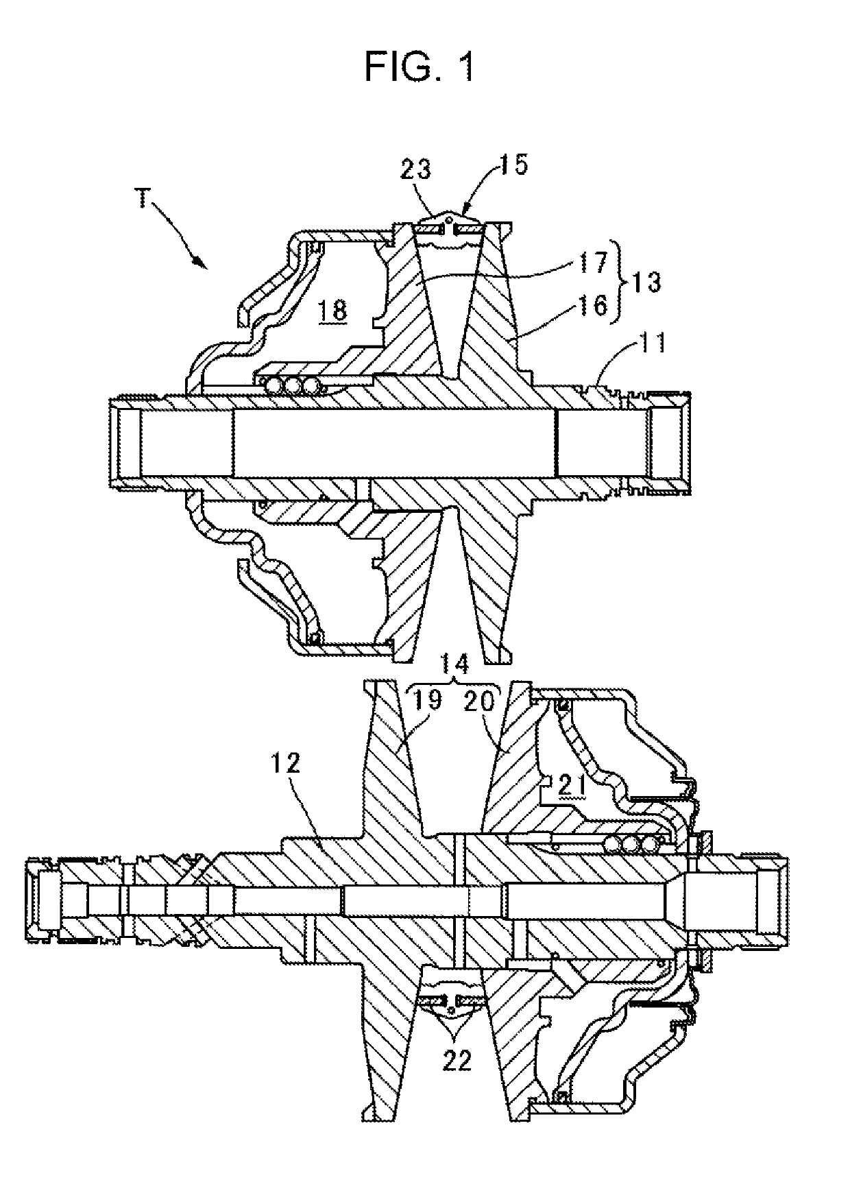
[0034]FIG. 1 illustrates a schematic structure of a belt-type continuously variable transmission T mounted on an automobile. The belt-type continuously variable transmission T includes a drive shaft 11 connected to an engine, and a driven shaft 12 connected to a drive wheel, and an endless metal belt 15 is wound around a drive pulley 13 provided in the drive shaft 11 and a driven pulley 14 provided in the driven shaft 12. The drive pulley 13 includes a fixed half-pulley 16 fixed to the drive shaft 11, and a movable half-pulley 17 which is movable toward and away from the fixed half-pulley 16, and the movable half-pulley 17 is urged toward the fixed half-pulley 16 by the hydraulic pressure applied to an oil chamber 18. The driven pulley 14 includes a fixed half-pulley 19 fixed to the driven shaft 12, and a movable half-pulley 20 which is movable toward and away from the f...

second embodiment

[0055]Next a second embodiment of the present disclosure will be described with reference to FIG. 10.

[0056]Although the main punch 44 in the first embodiment includes the depressed section 44c for forming the projection section 24b in the metal element 23, a step section 44d is formed instead of the depressed section 44c in the second embodiment. The step section 44d corresponds to the depressed section 44c that is extended to a position equivalent to the radially inner end of the body section 24 of the metal element 23. The material, which is pressed out at the time of pressing the metal element 23, flows into the radially outer end section of the step section 44d only, and thus it is possible to form the projection section 24b extending in the right-left direction at the position of the radially outer end of the body section 24 of the metal element 23.

[0057]According to the embodiment, space is present between the press surface of the main punch 44 and the depressed section 24c of...

third embodiment

[0058]Next, a third embodiment of the present disclosure will be described with reference to FIGS. 11 to 13.

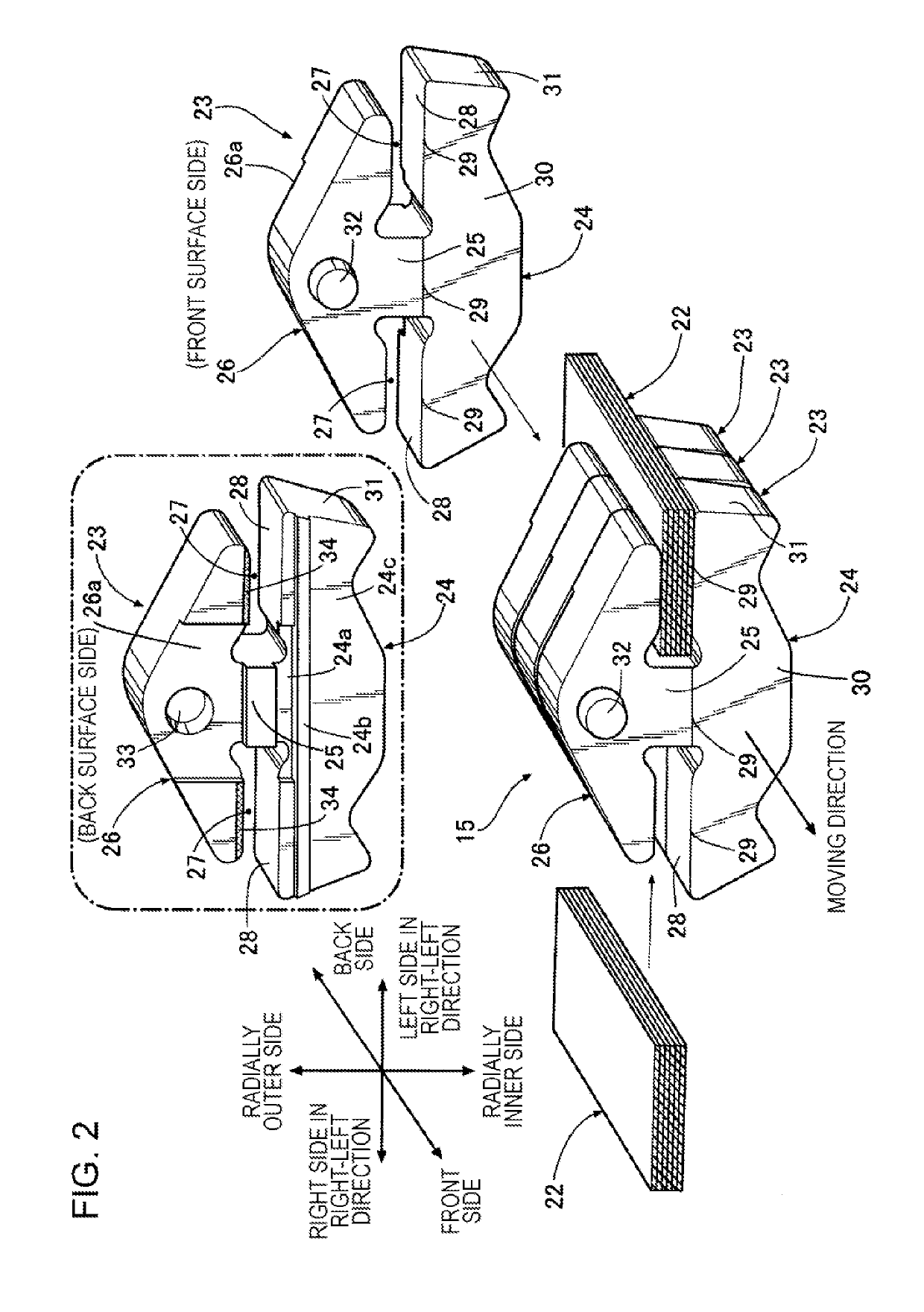
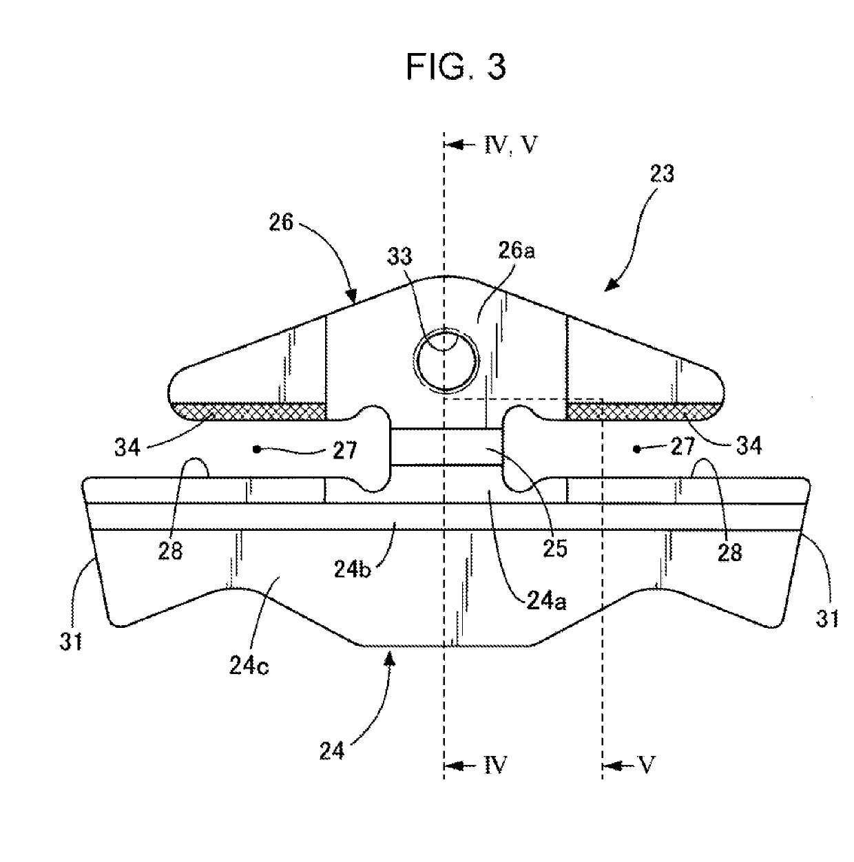
[0059]As illustrated in FIGS. 11 and 12, the back surface of the metal element 23 in the third embodiment includes the hole 33 at the center of the ear section 26, and the projection section 24b at the radially outer end of the body section 24, and the other sections are flat. In the embodiment, the function of the projection section 24b of the body section 24 is the same as the function of the projection section 24b of the body section 24 in the first and second embodiments, and the function compensates for decrease in the thickness of the vicinity of the locking edge 29 when barrel polishing is performed, and reduces the difference between the thicknesses of the ear section 26 and the body section 24.

[0060]As illustrated in FIG. 13, the punching device 41 in the embodiment has a feature in the press surface of the main punch 44, which machines the back surface of the metal e...


PUM

PropertyMeasurementUnit
heightaaaaaaaaaa
heightaaaaaaaaaa
shapeaaaaaaaaaa

Abstract

A metal element, which is pressed and punched by a mold, includes: a neck section positioned between a pair of right and left ring slots; an ear section continuous to a radially outer side of the neck section; and a body section continuous to a radially inner side of the neck section. A locking edge extending in a right-left direction is formed at a radially outer end of the front surface of the body section, and the metal element includes a projection section extending in the right-left direction on a back surface of the body section at a position backward of the locking edge.

Description

CROSS REFERENCES TO RELATED APPLICATIONS[0001]The present application claims priority under 35 U.S.C. § 119 to Japanese Patent Application No. 2018-071489, filed Apr. 3, 2018, entitled “Metal Element for Continuously Variable Transmission and Method of Manufacturing The Same.” The contents of this application are incorporated herein by reference in their entirety.BACKGROUND1. Field[0002]The present disclosure relates to a metal element for a continuously variable transmission, and a method of manufacturing the metal element. The metal element, which is pressed and punched by a mold, includes: a neck section positioned between a pair of right and left ring slots; an ear section continuous to a radially outer side of the neck section; and a body section continuous to a radially inner side of the neck section. A locking edge extending in a right-left direction is formed at a radially outer end of the front surface of the body section.2. Description of the Related Art[0003]A method of m...

Claims


Application Information

Patent Timeline
Patent Type & Authority Applications(United States)
IPC IPC(8): F16G5/16B21D22/02B21D53/14
CPCB21D22/02B21D53/14F16G5/16B21D37/10F16G5/20F16H9/12
Inventor YAGASAKI, TORU
Owner HONDA MOTOR CO LTD
Why Eureka
Try Eureka