Power toothbrush

a power toothbrush and power technology, applied in the field of power toothbrushes, can solve the problems of limiting the effect moving the drive shaft, etc., and achieve the effect of increasing the efficiency of removing dental plaque by the power toothbrush, high speed, and transmitting the driving force of the first magnetic circui

Inactive Publication Date: 2005-10-27
MATSUSHITA ELECTRIC WORKS LTD
View PDF9 Cites 64 Cited by
  • Summary
  • Abstract
  • Description
  • Claims
  • Application Information

AI Technical Summary

Benefits of technology

[0006] By such a configuration, the drive shaft is directly driven by the first magnetic circuit and the second magnetic circuit without intervening mechanical elements such as a cam and / or gears. Thus, efficiencies for transmitting driving forces from the first magnetic circuit and the second magnetic circuit to the drive shaft can be increased, so that the drive shaft can be driven in a high speed.
[0007] Furthermore, the drive shaft is driven by not only the first magnetic circuit in the axial direction thereof but also the second magnetic circuit around the center axis thereof. Thus, the motion of the brush head is not limited to only one of the reciprocal linear motion and the reciprocal rotation differ from the conventional power toothbrush. The brush head can be moved in a complex motion in combination with the reciprocal linear motion and the reciprocal rotation. As a result, an efficiency for removing dental plaque by the power toothbrush can be increased.

Problems solved by technology

Thus, it is difficult to move the drive shaft of the motion converting mechanism in a high speed, so that there is a limit to increase an effect for removing dental plaque.

Method used


Image

  • Power toothbrush
  • Power toothbrush
  • Power toothbrush

Examples


Embodiment Construction

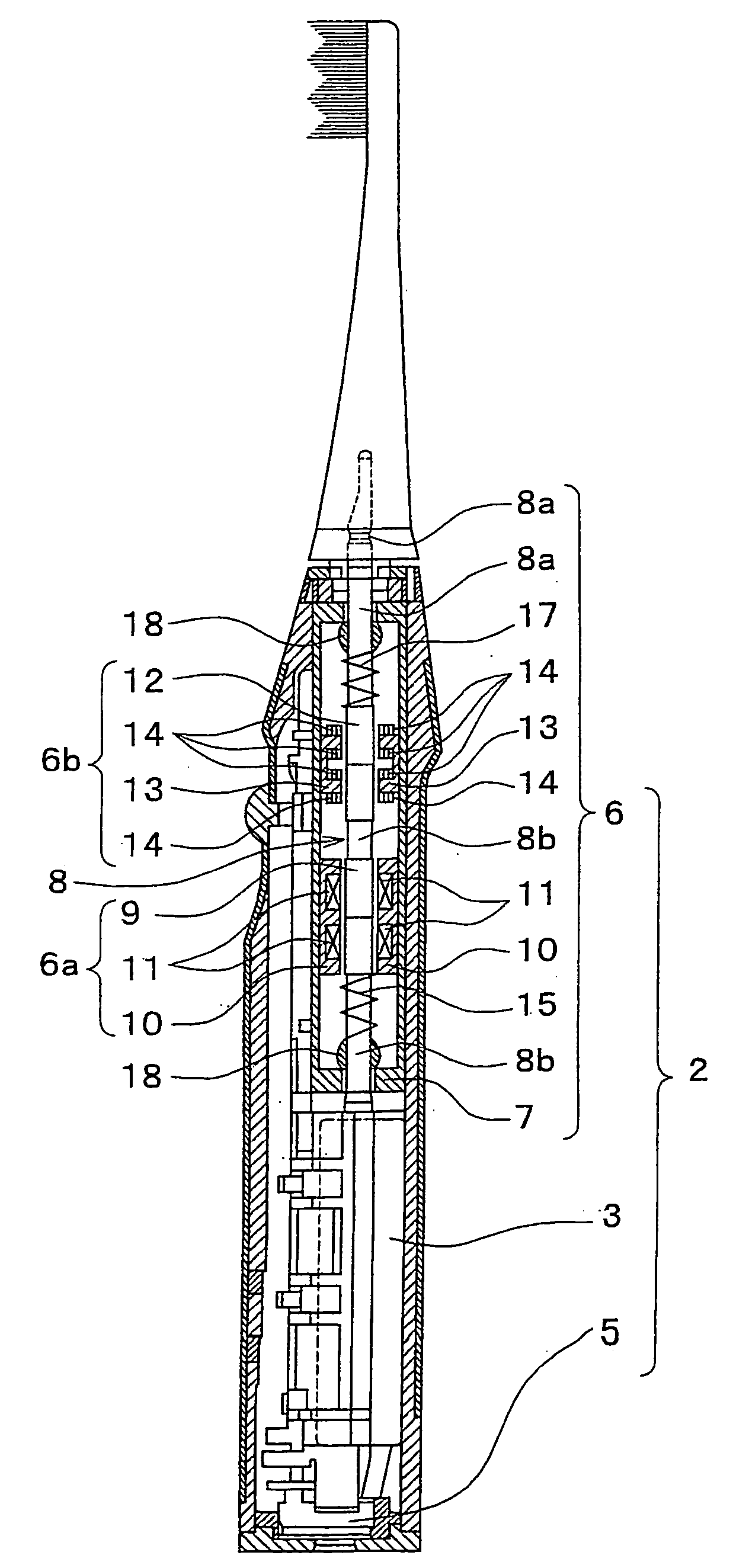
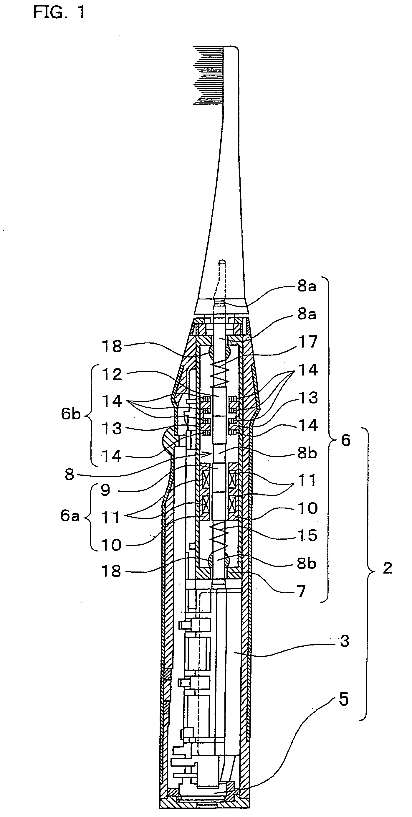
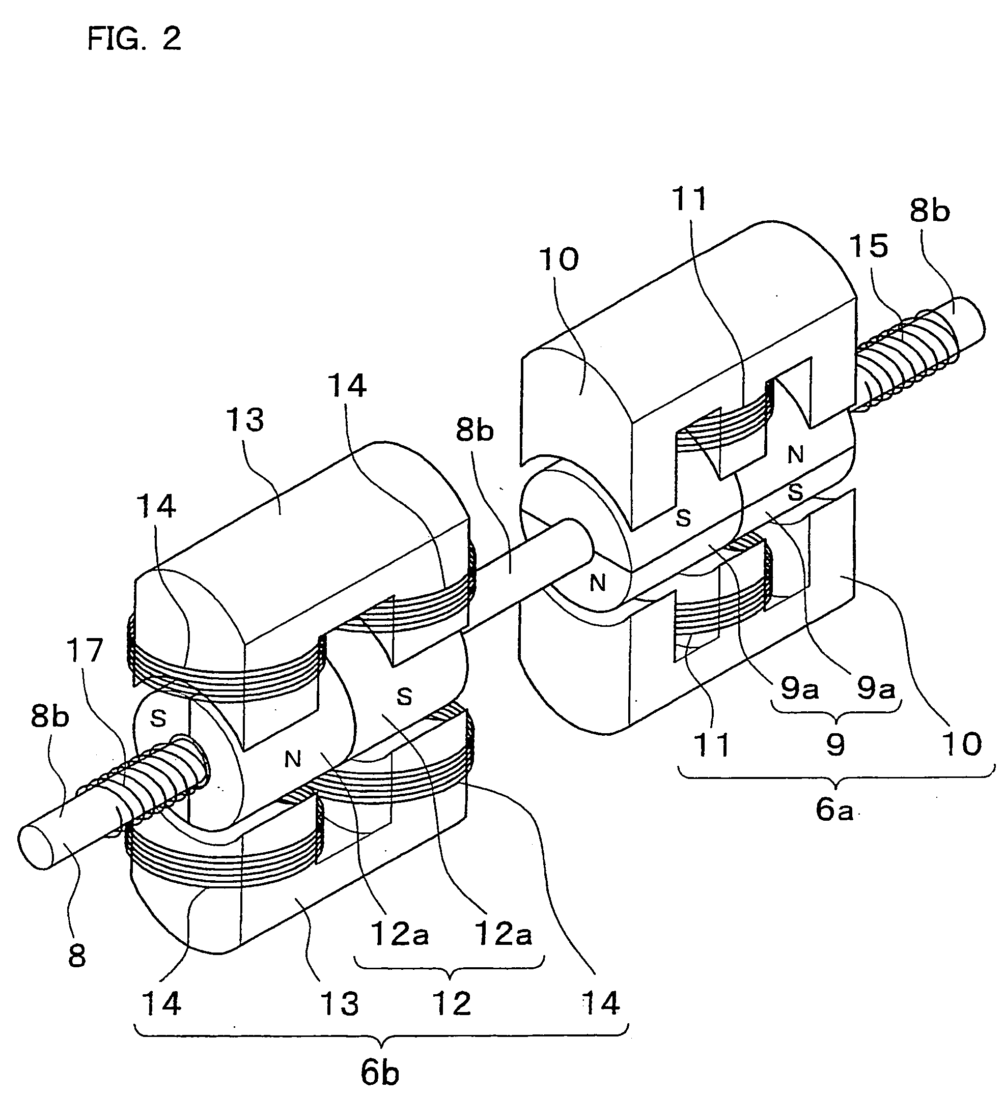
[0013] An embodiment of the present invention is described with reference to the drawings. FIG. 1 shows a configuration of a power toothbrush. FIG. 2 shows a detailed configuration of an actuator of the power toothbrush. FIG. 3 shows a first magnetic circuit in the actuator. FIG. 4 shows a second magnetic circuit in the actuator.

[0014] As can be seen from FIG. 1, the power toothbrush comprises a brush head 1 and a main body (grip portion) 2. The main body 2 further comprises an actuator 6 for moving the brush head 1, a controller (not shown) for controlling the actuator 6, a secondary cell (battery) 3, an inverter (not shown) for generating driving currents, a charging unit 5 for charging the secondary cell 3, and so on.

[0015] The actuator 6 further comprises a drive shaft 8, a first magnetic circuit 6a, a second magnetic circuit 6b, two coil springs 15 and 17. The substance of the actuator 6 is contained in a tubular casing 7. A front end portion 8a of the drive shaft 8 is protru...


PUM


Abstract

In a power toothbrush, an interchangeable brush head is directly fitted to a front end portion of a drive shaft of an actuator. The actuator comprises a first magnetic circuit for moving the drive shaft reciprocally in an axial direction of the drive shaft, and a second magnetic circuit for rotating the drive shaft around a center axis of the drive shaft. The first magnetic circuit and the second magnetic circuit are independently excited by independent driving current having predetermined frequencies and a predetermined phase difference therebetween. Thus, the brush head fitted to the drive shaft can be moved in a composition of reciprocal linear movement and reciprocal rotation. The actuator does not include conventional mechanical elements such as gears or cams so that the actuator can move the drive shaft much faster than that of the conventional actuator.

Description

TECHNICAL FIELD [0001] The present invention relates to a power toothbrush, and especially relates to an actuator for reciprocally moving a brush head in an axial direction of a drive shaft and for reciprocally rotating the brush head around a center axis of the drive shaft. BACKGROUND ART [0002] In a conventional power toothbrush, for example, shown in publication of Japanese patent application 9-173360, rotation of a drive shaft of a motor is converted to reciprocal linear motion or reciprocal rotation by a motion converting mechanism. A brush head fitted on a drive shaft of the motion converting mechanism is reciprocally moved in an axial direction of the drive shaft or reciprocally rotated around a center axis of the drive shaft. [0003] The conventional power toothbrush, however, uses a cam in the motion converting mechanism for converting the continuous rotation of the drive shaft of the motor to reciprocal linear movement or reciprocal rotation of the drive shaft of the motion...

Claims


Application Information

Patent Timeline
Patent Type & Authority Applications(United States)
IPC IPC(8): A61C17/34H02K33/16
CPCA61C17/3418A61C17/3445H02K2201/18H02K33/16A61C17/3472A61C17/34
Inventor MOTOHASHI, RYOKUNITA, TOMOHIROTANIGUCHI, SHINICHIHIRATA, KATSUHIROHASEGAWA, YUYA
Owner MATSUSHITA ELECTRIC WORKS LTD
Why Eureka
Try Eureka