Recycled purge air dryer system and method of use
- Summary
- Abstract
- Description
- Claims
- Application Information
AI Technical Summary
Benefits of technology
Problems solved by technology
Method used
Image
Examples
Embodiment Construction
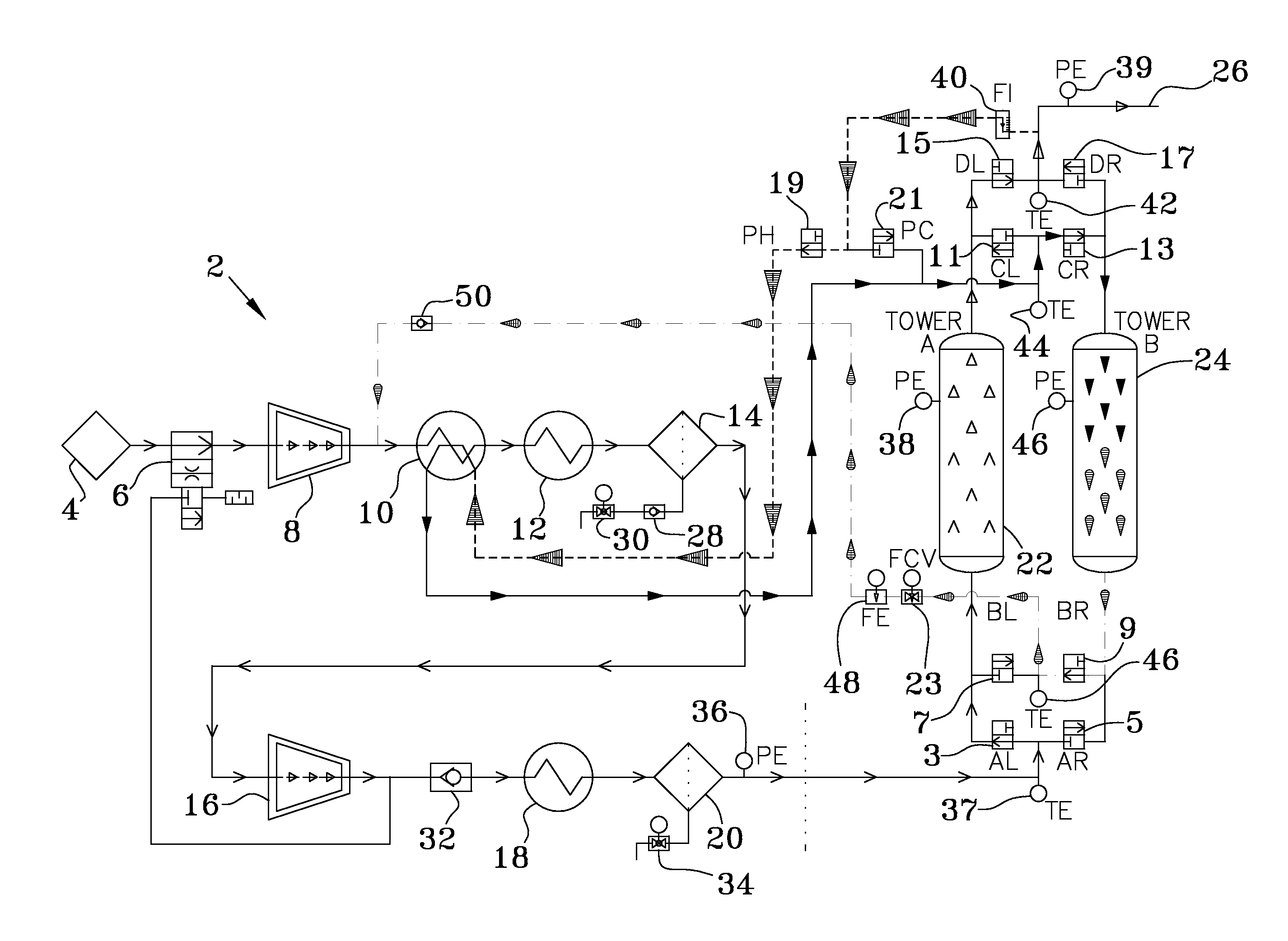
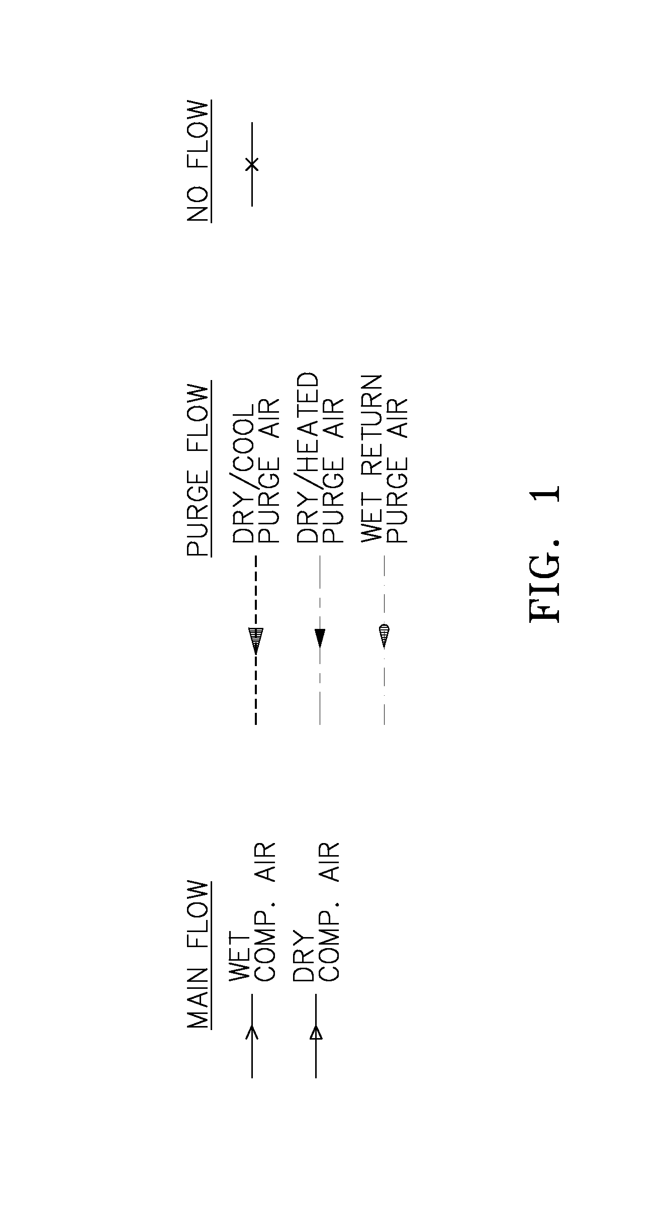
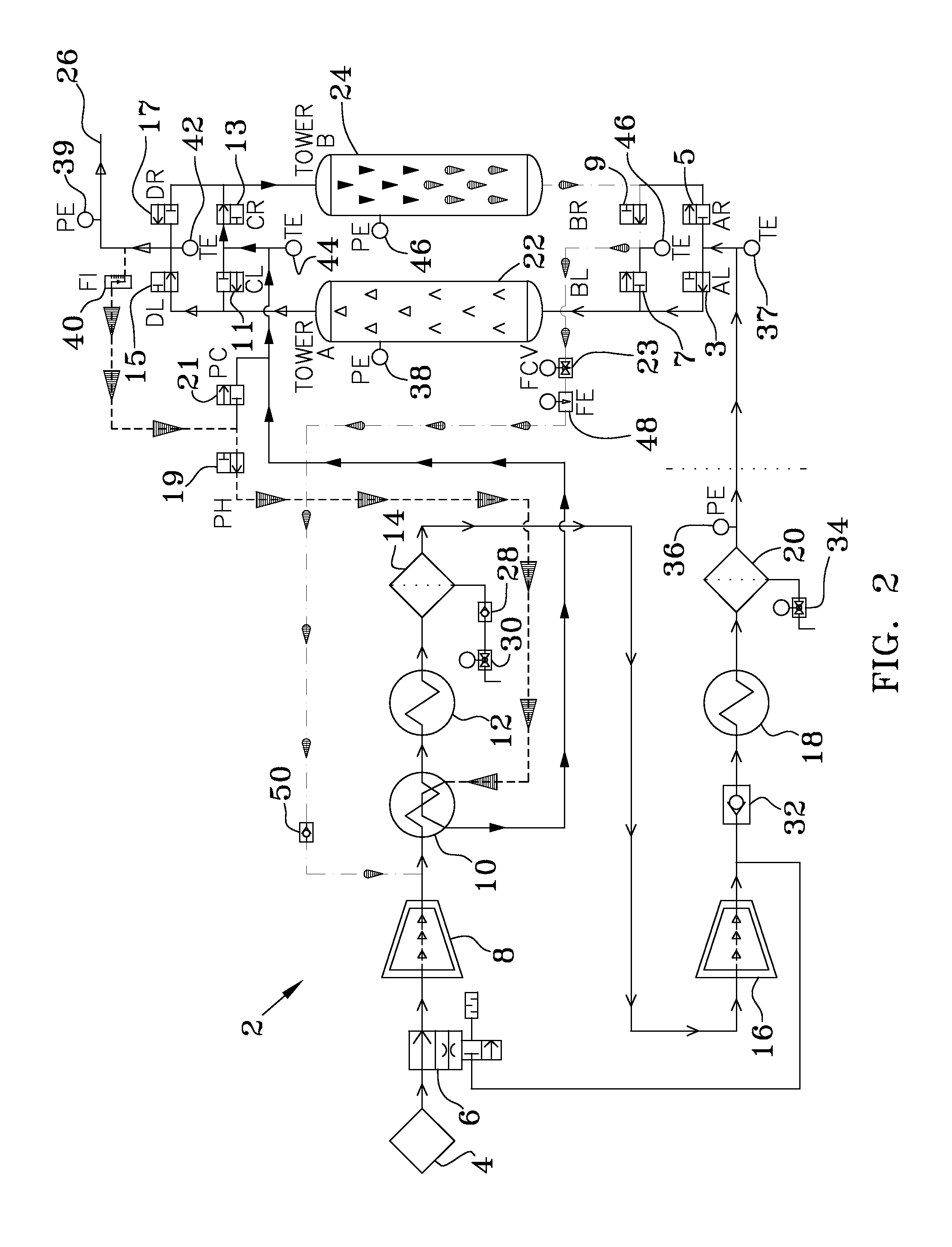
[0020]A recycled purge dryer and method of use according to the present invention is illustrated in FIGS. 1-11. As will be discussed in further detail below, FIGS. 1-11 illustrate multiple flow paths, as directed through various valves, through the various components of the recycled purge dryer system 2. Looking at FIG. 1-11 it can be seen that the recycled purge dryer system 2 comprises a wet air inlet (not shown), an inlet filter 4, a loaded capacity control valve 6, a first stage compressor 8, a purge air heat exchanger 10, an intercooler 12, an intercooler separator 14, a second stage compressor 16, an aftercooler 18, an aftercooler separator 20, a pair of drying towers, 22 and 24, and a dry air outlet 26. Drying Towers 22 and 24 are filled with a desiccant (not shown). A conduit structure interconnects all aforementioned components. Ten valves are of specific interest to this disclosure, reside at varying points along the conduit structure, and can be open or closed to alter th...
PUM
 Abstract
Description
Claims
Application Information
 - R&D
- Intellectual Property
- Life Sciences
- Materials
- Tech Scout
- Unparalleled Data Quality
- Higher Quality Content
- 60% Fewer Hallucinations
Browse by: Latest US Patents, China's latest patents, Technical Efficacy Thesaurus, Application Domain, Technology Topic, Popular Technical Reports.
© 2025 PatSnap. All rights reserved.Legal|Privacy policy|Modern Slavery Act Transparency Statement|Sitemap|About US| Contact US: help@patsnap.com


