

Support for solar energy collection
a solar energy collection and solar energy technology, applied in the direction of solar heat collector controllers, rigid support of bearing units, electrical equipment, etc., can solve the problems of difficult alignment, large components of sun-tracking solar systems, and large weight of solar energy collection systems, so as to simplify the bearings of sun-tracking solar energy collection systems
- Summary
- Abstract
- Description
- Claims
- Application Information
AI Technical Summary
Benefits of technology
Problems solved by technology
Method used
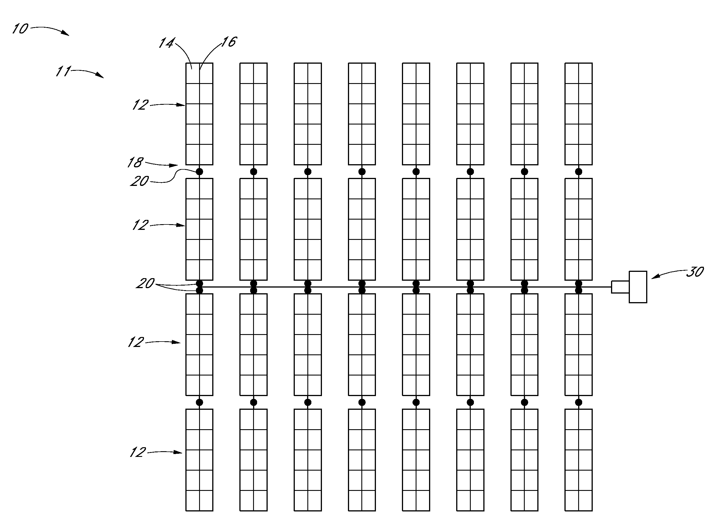
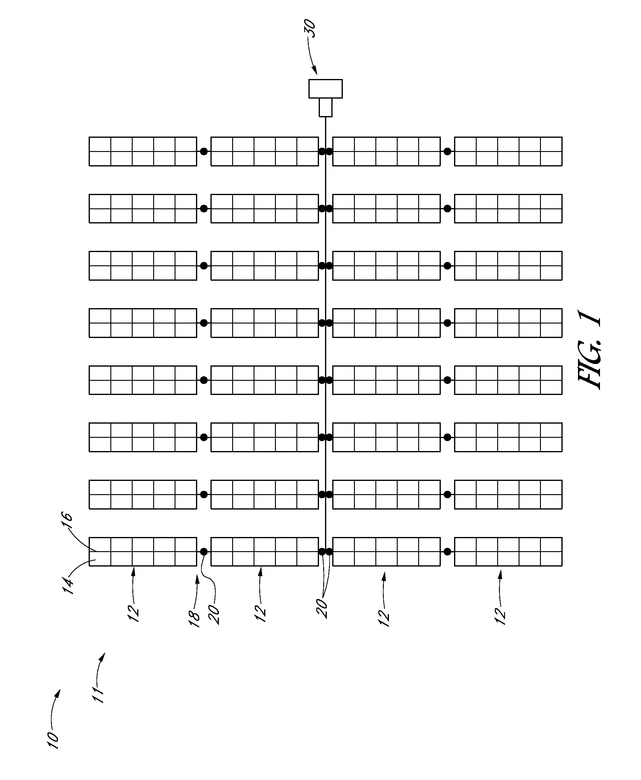
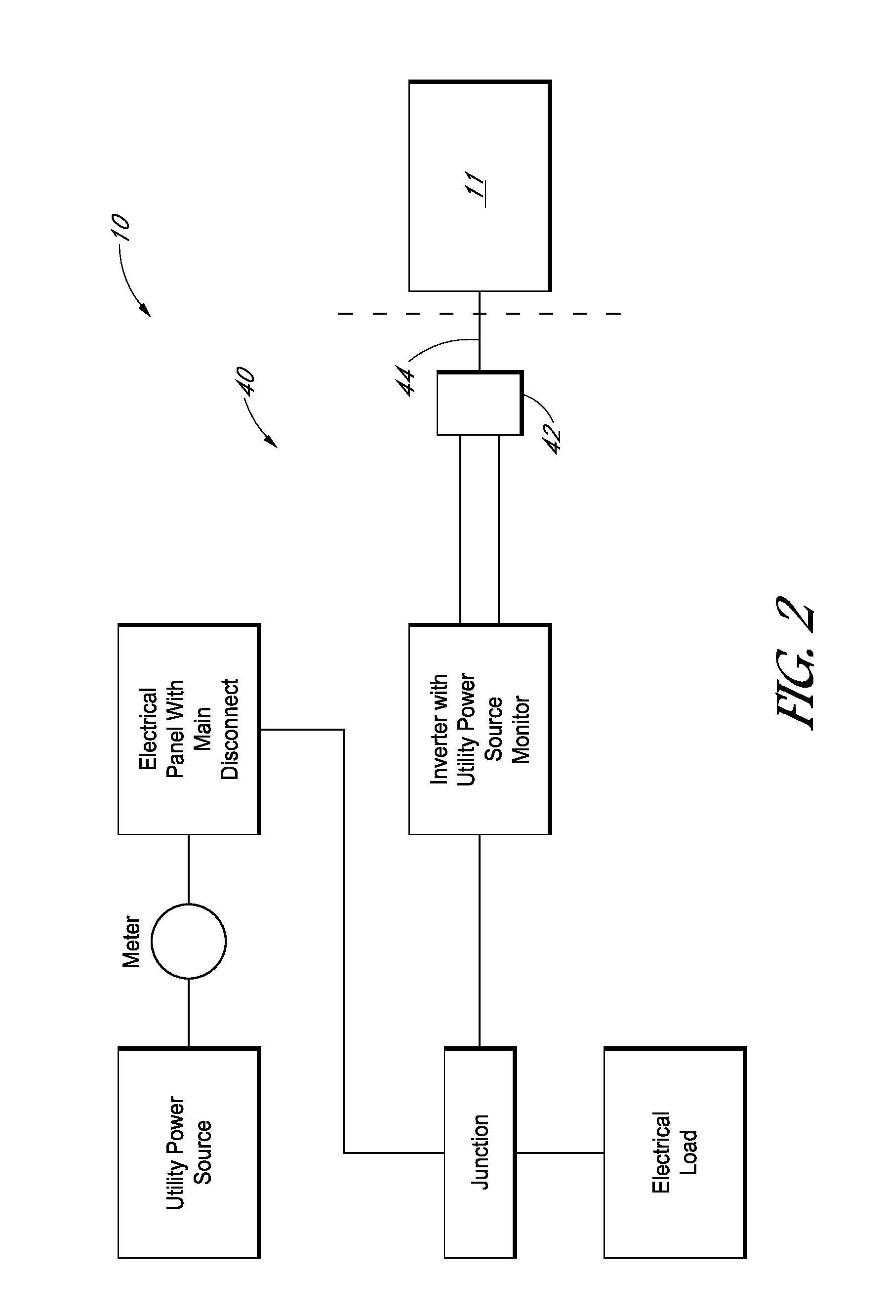
Image

Examples
Embodiment Construction
[0040]The following detailed description is merely illustrative in nature and is not intended to limit the embodiments of the subject matter or the application and uses of such embodiments. As used herein, the word “exemplary” means “serving as an example, instance, or illustration.” Any implementation described herein as exemplary is not necessarily to be construed as preferred or advantageous over other implementations. Furthermore, there is no intention to be bound by any expressed or implied theory presented in the proceeding technical field, background, brief summary, or the following detailed description.
[0041]Certain terminology may be used in the following description for the purpose of reference only, and thus are not intended to be limiting. For example, terms such as “upper”, “lower”, “above”, and “below” refer to directions in the drawings to which reference is made. Terms such as “front”, “back”, “rear”, and “side” describe the orientation and / or location of portions of...
PUM
| Property | Measurement | Unit |
|---|---|---|
| outer diameter | aaaaa | aaaaa |
| outer diameter | aaaaa | aaaaa |
| outer diameter | aaaaa | aaaaa |
Abstract
Description
Claims
Application Information