Vehicular electric drive apparatus

a technology of electric drive and electric motor, which is applied in the direction of electric propulsion mounting, mechanical actuated clutches, electric propulsion mounting, etc., can solve the problems of difficulty in optimum oil supply, large amount of insufficient oil supply for the other electric motor and gear mechanism. , to achieve the effect of preventing a shortage of supply and improving fuel economy

Active Publication Date: 2014-09-18
TOYOTA JIDOSHA KK
View PDF5 Cites 44 Cited by
  • Summary
  • Abstract
  • Description
  • Claims
  • Application Information

AI Technical Summary

Benefits of technology

[0007]The vehicular electric drive system described above is configured such that the oil delivered from the oil pump is supplied to the hydraulically operated clutch and the electric motor accommodated in the first chamber. Accordingly, it is possible to prevent a shortage of supply of the oil to the hydraulically operated clutch and the electric motor. On the other hand, the gear mechanism accommodated in the second chamber and lubricated by the oil does not require a large amount of the oil, and is therefore lubricated by another independent oil supply mechanism of a splash type, for example. Thus, the first chamber is supplied with the pressurized oil delivered from the oil pump, while the second chamber is supplied with the oil by the oil supply mechanism not using the oil pump, whereby only the required amounts of the oil are supplied to the first and second chambers, so that the fuel economy can be improved.
[0008]According to a second aspect of this invention, the vehicular electric drive system according to the first aspect of the invention is configured such that the above-described gear mechanism is a transmission having two speed positions, and the above-described hydraulically operated clutch is a dual clutch consisting of two frictional coupling devices, and such that the above-described transmission is shifted between the two speed positions, by switching operating states of the two frictional coupling devices. According to this second aspect of the invention, the transmission can be shifted by simply controlling the frictional coupling devices, without using shift forks and sleeves for the shifting actions, so that the vehicular electric drive system can be made simple in construction.
[0009]According to a third aspect of the invention, the vehicular electric drive system according to the second aspect of the invention is configured such that the above-described oil pump is driven by the above-described electric motor, and one of the above-described frictional coupling devices which is placed in an engaged state upon starting of a vehicle is a frictional coupling device of a normally-engaged type which is placed in the engaged state when a hydraulic pressure is not applied thereto. According to this third form of the invention, the vehicle can be rapidly started without the hydraulic pressure application to the frictional coupling device to be placed in the engaged state to start the vehicle although the electric motor and the oil pump are not driven upon starting of the vehicle, thus the hydraulic pressure application to the above-indicated frictional coupling device would be delayed.

Problems solved by technology

Where the electric motor is accommodated in a space also accommodating the gear mechanism, for simply cooling of the electric motor with the oil, different amounts of the oil are required for respectively cooling the electric motor and the gear mechanism, so that if an oil supply device is designed on the basis of the amount of the oil required for the electric motor or the gear mechanism, this amount is larger than required or insufficient for the other of the electric motor and the gear mechanism.
Where the vehicular electric drive apparatus is provided with a transmission mechanism having hydraulically operated clutches, different amounts of the oil are required for respectively cooling the electric motor, the gear mechanism and the transmission mechanism, giving rise to a problem of difficult supply of the optimum amounts of the oil to the respective parts of the vehicular electric drive apparatus.

Method used


Image

  • Vehicular electric drive apparatus
  • Vehicular electric drive apparatus
  • Vehicular electric drive apparatus

Examples


first embodiment

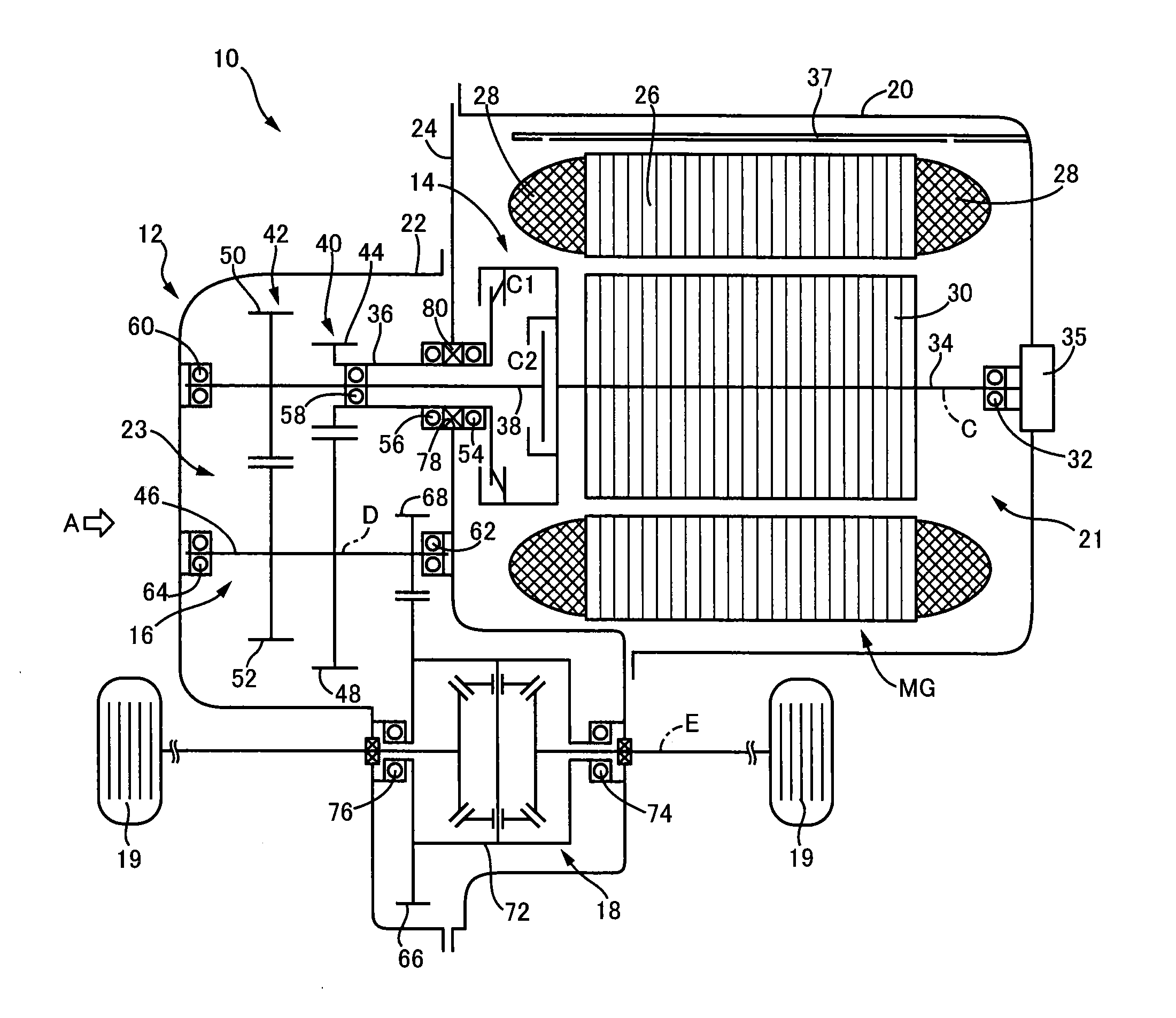
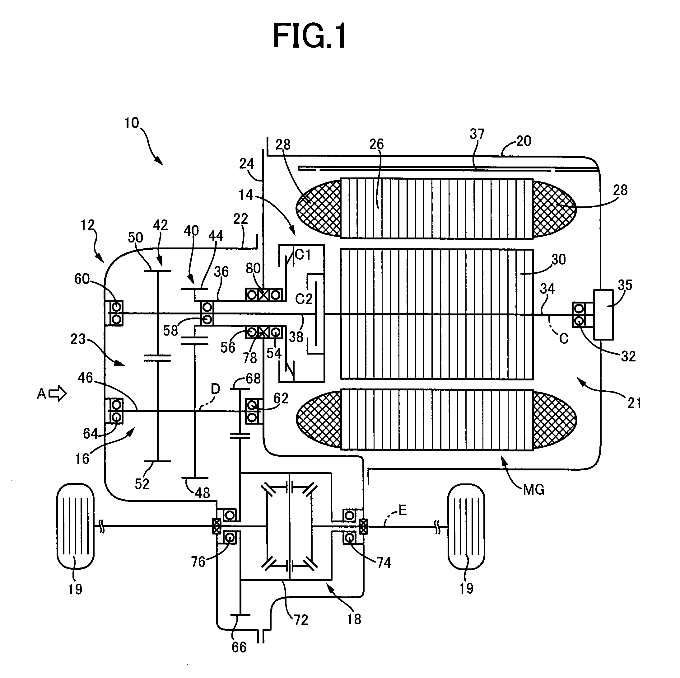
[0013]FIG. 1 is the cross sectional view of a vehicular electric drive system 10 (hereinafter referred as an “electric drive system 10”) according to one embodiment of this invention. The electric drive system 10 is provided with major components including an electric motor MG, a dual clutch 14, a speed reducing gear mechanism 16 and a differential device 18, which are accommodated within an axle casing 12. In the electric drive system 10, the electric motor MG is operatively connected to drive wheels 19 through the dual clutch 14, speed reducing gear mechanism 16 and differential device 18, so that the drive wheels 19 are driven by the electric motor MG.

[0014]The axle casing 12 consists of a first casing 20 accommodating the electric motor MG and the dual clutch 14 as the major components, a second casing 22 having a tubular shape with a closed end and accommodating the speed reducing gear mechanism 16 as the major component, and a partition wall 24 which isolates the first casing ...

second embodiment

[0038]Another embodiment of this invention will be described. It is noted that the same reference signs as used in the preceding embodiment will be used to identify the same elements in the present embodiment.

[0039]In the preceding embodiment, the same kind of oil is used in the first chamber 21 and the second chamber 23. In the present embodiment, different kinds of oil are used in the first and second chambers 21 and 23. In the other aspects, the present embodiment is identical with the preceding embodiment, and will not be described with respect to those aspects. In the present embodiment, an oil of the kind suitable for controlling the dual clutch 14 and cooling the electric motor MG is used in the first chamber 21, while an oil of the kind suitable for lubricating the speed reducing gear mechanism 16 is used in the second chamber. Like the preceding embodiment, the present embodiment using the two different kinds of oil has the advantage that only the required amounts of the oi...


PUM


Abstract

A vehicular electric drive system comprises: an electric motor operatively connected to drive wheels so that the drive wheels are driven by said electric motor; a hydraulically operated clutch configured to place a power transmitting path between said electric motor and said drive wheels in a selected one of a power transmitting state and a power cutoff state; a gear mechanism disposed between said hydraulically operated clutch and said drive wheels, to reduce a speed of a rotary motion of said electric motor; a first chamber accommodating said electric motor and said hydraulically operated clutch; a second chamber accommodating said gear mechanism; a partition wall disposed so as to isolate said first chamber and said second chamber from each other; a connecting hole formed on said partition wall through which said hydraulically operated clutch and said gear mechanism are operatively connected to each other; an oil seal fitted in said connecting hole, to restrict flows of an oil through said connecting hole; an oil pump provided to deliver the oil required within said first chamber; and another independent oil supply mechanism which does not use said oil pump and which is provided to supply the oil to said second chamber.

Description

TECHNICAL FIELD[0001]The present invention relates to an arrangement of a vehicular electric drive apparatus.BACKGROUND ART[0002]There is well known a vehicular electric drive apparatus wherein an electric motor is operatively connected to drive wheels so that the drive wheels are driven by the electric motor. Patent Document 1 discloses an example of such a vehicular electric drive apparatus in the form of an auxiliary drive device 20 of a main drive device 10. The auxiliary drive device 20 of Patent Document 1 is provided with major components including an electric motor 20a, a speed reducing gear train 20b (gear mechanism) for reducing the operating speed of the electric motor 20a, and a differential device 20d. The electric motor 20a is used to drive rear wheels 21b (drive wheels). The electric motor 20a is isolated from the speed reducing gear train 20b by an axle casing 24.PRIOR ART DOCUMENTPatent Document[0003]Patent Document 1: JP-2005-263208 ASUMMARY OF THE INVENTIONObject ...

Claims


Application Information

Patent Timeline
Patent Type & Authority Applications(United States)
IPC IPC(8): F16D25/10
CPCF16D25/10F16H57/0445F16H57/0457F16H57/0473F16H57/0476F16H57/0483B60K2001/001F16D21/06Y02T10/72F16H2200/0034F16H2200/0021F16H3/006
Inventor SUGIYAMA, MASATAKAKIMURA, HIROAKI
Owner TOYOTA JIDOSHA KK
Why Eureka
Try Eureka