
Laser optics with lateral and angular shift compensation

a technology of angular shift compensation and laser optics, which is applied in the direction of metal-working equipment, welding equipment, manufacturing tools, etc., can solve the problems of reoccurring constrictions or blockages, exacerbate the occurrence of restenosis or thrombosis, and thicker or thinner struts, so as to reduce the need for time-consuming alignment procedures, improve the efficiency of the cutting process, and reduce the effect of time-consuming

Inactive Publication Date: 2014-09-18
ABBOTT CARDIOVASCULAR
View PDF6 Cites 6 Cited by
  • Summary
  • Abstract
  • Description
  • Claims
  • Application Information

AI Technical Summary

Benefits of technology

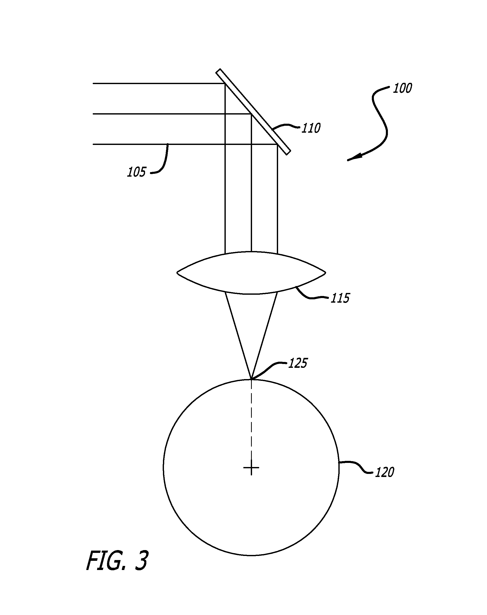
The invention is a laser cutting system that uses a special lens to improve the efficiency of stent cutting. The system eliminates the need for time-consuming alignment procedures and is particularly useful with short pulse lasers. It also includes a method for detecting the position of the laser beam and repositioning it to improve the accuracy of the cutting process. Overall, the invention makes the stent cutting process faster, more efficient, and accurate.

Problems solved by technology

Although the stents are effective in opening the stenotic lumen, the foreign material and structure of the stents themselves may exacerbate the occurrence of restenosis or thrombosis.
Although PTCA and related procedures aid in alleviating intraluminal constrictions, such constrictions or blockages reoccur in many cases.
When this occurs, there are two primary resulting defects.
First, the cutting spot differs from the anticipated position and so the cut stent pattern may differ from the programmed pattern, which may cause thicker or thinner struts.
Second, the beam may become defocused at the surface of the stent tube due to change in position of the cutting spot.
Additionally, because the beam is directed through the stent tubing at an angle, the resulting strut walls may not be perpendicular to the outer surface, which can cause the inner or outer strut width to differ from the desired dimension and result in variable stent strength.
Furthermore, even if the laser beam is directed perpendicular to the cutting surface, there is currently no method of quickly and effectively checking the beam position and alignment or of adjusting those characteristics.
The typical process for such realignment and repositioning requires a time consuming sequence of manually checking and observing the beam position and independently adjusting various components of the optical chain until the necessary beam position and alignment is achieved.
The current process requires a stage-assistant alignment between the laser beam and stent tube that is costly and inefficient.
This process introduces significant manufacturing inefficiencies that negatively impact the efficiency of stent manufacturing.

Method used


Image

  • Laser optics with lateral and angular shift compensation
  • Laser optics with lateral and angular shift compensation
  • Laser optics with lateral and angular shift compensation

Examples


Embodiment Construction

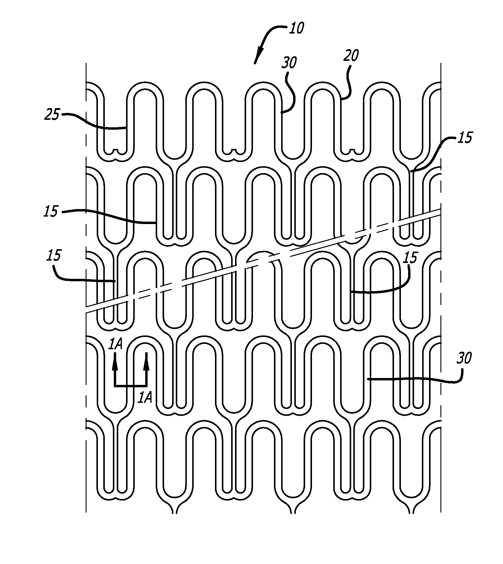
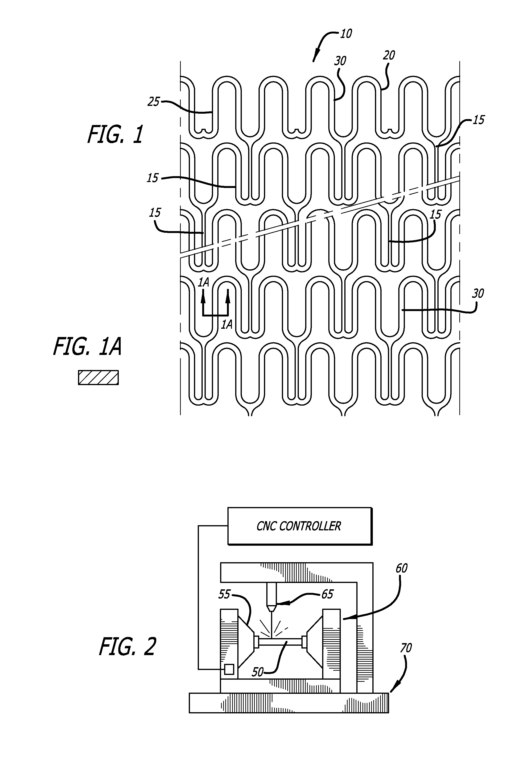
[0042]FIG. 1 is an enlarged perspective view of a stent 10 illustrating an exemplary stent pattern and showing the placement of interconnecting elements 15 between adjacent radially expandable cylindrical elements. Each pair of the interconnecting elements 15 on one side of a cylindrical element are preferably placed to achieve maximum flexibility for a stent. In the embodiment shown in FIG. 1, the stent 10 has three interconnecting elements 15 between adjacent radially expandable cylindrical elements which are 120 degrees apart. Each pair of interconnecting elements 15 on one side of a cylindrical element are offset radially 60 degrees from the pair on the other side of the cylindrical element. The alternation of the interconnecting elements results in a stent which is longitudinally flexible in essentially all directions. Various configurations for the placement of interconnecting elements are possible. However, as previously mentioned, all of the interconnecting elements of an in...


PUM

PropertyMeasurementUnit
outer diameteraaaaaaaaaa
thicknessaaaaaaaaaa

Abstract

A telecentric F-theta lens is added to the optical chain of a laser used to cut stent patterns into a stent tube to facilitate positioning and alignment of the laser beam and to compensate for lateral and angular shift of the beam spot.

Description

CROSS-REFERENCES TO RELATED APPLICATIONS[0001]This application claims priority from U.S. Application No. 61 / 798,651, filed Mar. 15, 2013 incorporated by reference in its entirety.BACKGROUND[0002]1. Field of the Invention[0003]The present invention relates generally to implantable medical devices and to a method for manufacturing implantable medical devices. These implantable medical devices may also be capable of retaining therapeutic materials and dispensing the therapeutic materials to a desired location of a patient's body. More particularly, the present invention relates to a system and method for forming the structure of a stent or intravascular or intraductal medical device, and IS particularly related to a combination of optical components used to compensate for lateral and angular shift of a laser beam used to form the stent structure from a tube.[0004]2. General Background and State of the Art[0005]In a typical percutaneous transluminal coronary angioplasty (PTCA) for compr...

Claims


Application Information

Patent Timeline
Patent Type & Authority Applications(United States)
IPC IPC(8): B23K26/02A61F2/91
CPCA61F2/91B23K26/026B23K26/0643B23K26/0648B23K26/38B23K26/032B23K26/707
Inventor CHEN, LI
Owner ABBOTT CARDIOVASCULAR
Learn More