
Gas Phase Alloying for Wire Fed Joining and Deposition Processes

Active Publication Date: 2014-09-18
NASA
View PDF9 Cites 16 Cited by
  • Summary
  • Abstract
  • Description
  • Claims
  • Application Information

AI Technical Summary

Benefits of technology

The present invention is a method of fabricating an object by controlling the distribution of material properties during fabrication. This is achieved by adding and solidifying molten metal in a controlled manner to achieve a predefined non-uniform distribution of material properties. The method can be used to fabricate objects such as aircraft structural components with specific material properties such as yield strength, hardness, and fracture toughness. The molten pools of metal can be formed by melting hollow wires or solid wires and controlling the composition and grain structure through the addition of process gas. The method can also involve using an electron beam in a vacuum or welding to control the material properties of the molten pools. Overall, the method allows for the fabrication of objects with precise material properties.

Problems solved by technology

However, in use, the material of a component may be subject to uneven stress levels or other environmental factors.
However, adding material in high stress areas may result in additional weight.
However, in some situations, substitution of a higher strength material may not be feasible if the higher strength material has other properties that are incompatible with the design requirements for the component.
However, these techniques may suffer from various metallurgical limitations.
These limitations include coarse, cast-like microstructures, vaporization of volatile alloying elements, and other detrimental metallurgical effects.
However, this solution is generally limited to common alloys with widespread use in welded structures where modified wire is commercially available.
For other materials, specialty wire with modified chemistry may be impractical due to the inability to draw the composition into wire form and / or the prohibitive expense in doing so.

Method used


Image

  • Gas Phase Alloying for Wire Fed Joining and Deposition Processes
  • Gas Phase Alloying for Wire Fed Joining and Deposition Processes
  • Gas Phase Alloying for Wire Fed Joining and Deposition Processes

Examples


Embodiment Construction

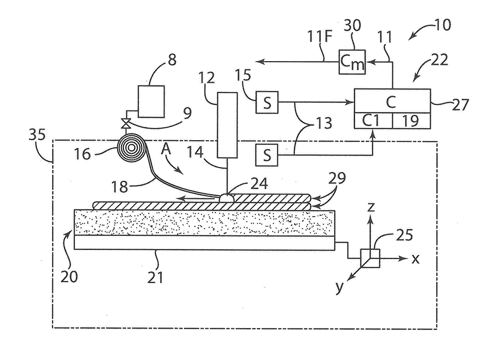
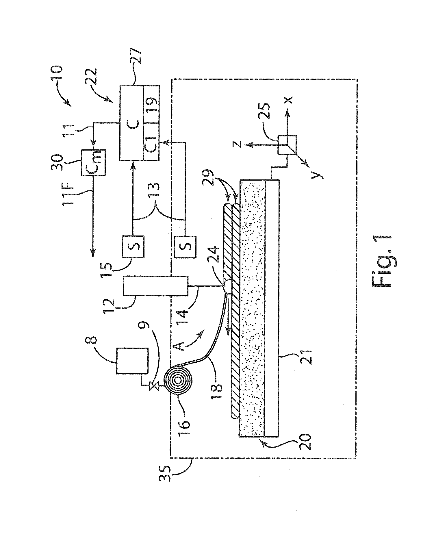
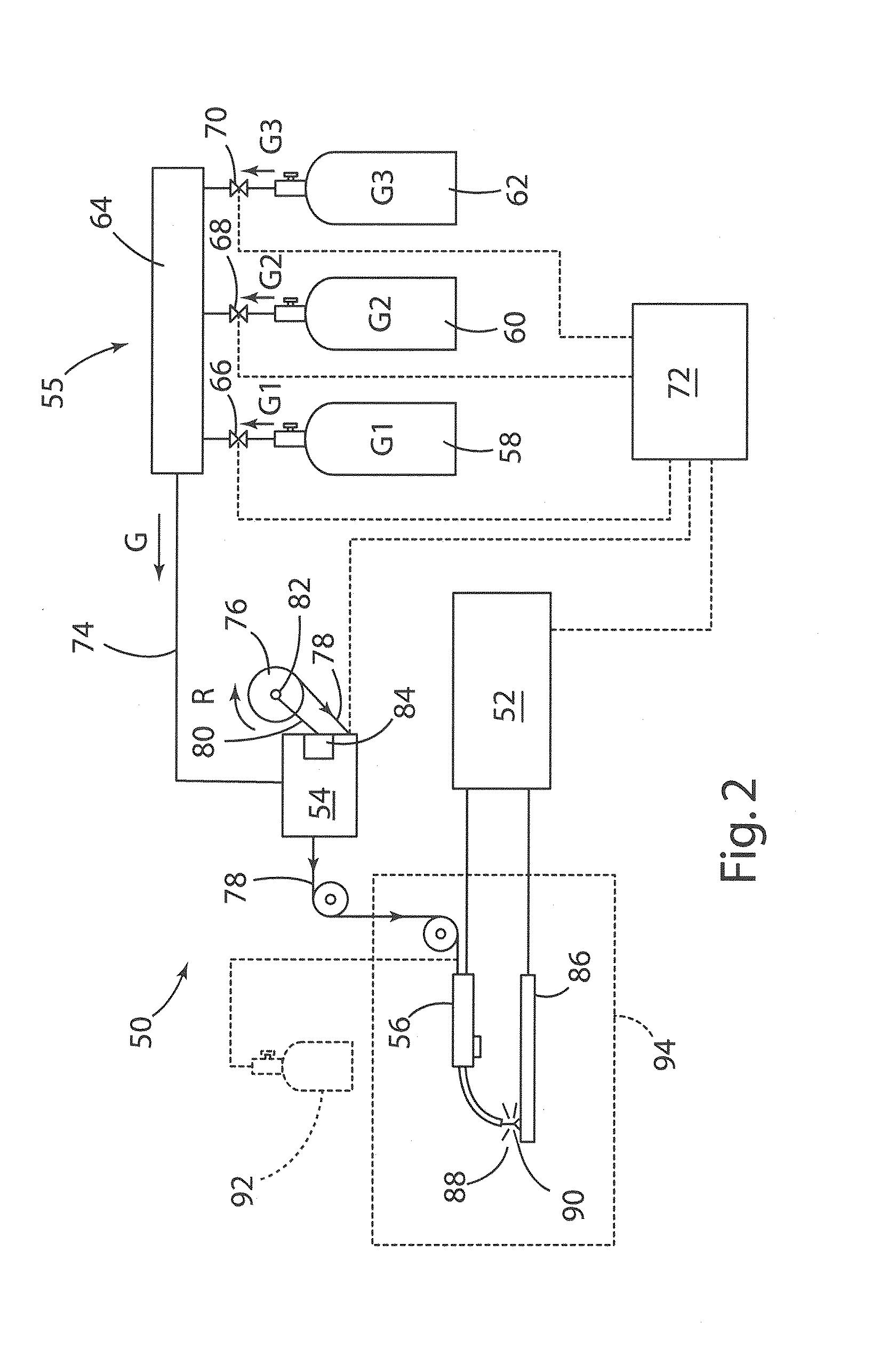
[0021]For purposes of description herein, the terms “upper,”“lower,”“right,”“left,”“rear,”“front,”“vertical,”“horizontal,” and derivatives thereof shall relate to the invention as oriented in FIGS. 1 and 2. However, it is to be understood that the invention may assume various alternative orientations and step sequences, except where expressly specified to the contrary. It is also to be understood that the specific devices and processes illustrated in the attached drawings, and described in the following specification, are simply exemplary embodiments of the inventive concepts defined in the appended claims. Hence, specific dimensions and other physical characteristics relating to the embodiments disclosed herein are not to be considered as limiting, unless the claims expressly state otherwise.

[0022]The present invention involves controlling the composition of metal or other material as an object is being fabricated to thereby control and / or vary the alloy composition throughout the ...


PUM

PropertyMeasurementUnit
Compositionaaaaaaaaaa
Flow rateaaaaaaaaaa
Fracture toughnessaaaaaaaaaa

Abstract

Gas is introduced into molten metal during an additive metal fabrication process and / or during a metal fusion process. The gas may comprise a process gas that flows through a tubular feed wire. The amount of process gas introduced can be controlled to vary the composition and / or material properties of metal deposits formed from a molten metal. Material properties such as yield strength, hardness, and fracture toughness can be increased or decreased in specific regions to provide material property gradients that closely correspond to expected requirements of components fabricated utilizing additive and / or fusion processes.

Description

CROSS-REFERENCE TO RELATED PATENT APPLICATION(S)[0001]This patent application claims the benefit of and priority to U.S. Provisional Patent Application No. 61 / 777,556, filed on Mar. 12, 2013, the contents of which are hereby incorporated by reference in their entirety.STATEMENT REGARDING FEDERALLY SPONSORED RESEARCH OR DEVELOPMENT[0002]The invention described herein was made by an employee of the United States Government and may be manufactured and used by or for the Government of the United States of America for governmental purposes without the payment of any royalties thereon or therefore.BACKGROUND OF THE INVENTION[0003]Metals and metal alloys have been widely used in fabricating a wide range of components. Metal components may be made by known processes such as casting, machining, roll forming, welding, and other such processes. Metal components may be made from metal having substantially uniform material properties. However, in use, the material of a component may be subject t...

Claims


Application Information

Patent Timeline
IPC IPC(8): B23K9/00C23C28/00C23C26/02
CPCB23K9/0008C23C28/30C23C26/02B23K15/0006B23K15/0086B23K15/0093B23K15/06C22C14/00C22C38/00B23K2103/14
Inventor BRICE, CRAIG A.
Owner NASA
Learn More