Unlock instant, AI-driven research and patent intelligence for your innovation.

Methods and apparatus for optically encoded position multiple-point scintillation detector using a single collecting light guide

Active Publication Date: 2014-09-18
UNIV LAVAL +1
View PDF7 Cites 5 Cited by
  • Summary
  • Abstract
  • Description
  • Claims
  • Application Information

AI Technical Summary

Benefits of technology

The patent describes a radiation dosimeter that can measure radiation dose at multiple points in a detection region. The dosimeter includes a radiation detector with multiple scintillating elements that generate optical energy in response to irradiation. A single collecting light guide optically couples the detector to the scintillating elements and receives and transmits the optical energy. A spectral filter stage optically decouples the optical energy and generates electrical signals indicative of the optical energy at different regions. A computing device processes the electrical signals to compute the measured radiation dose. The patent also describes a method for calibrating the dosimeter by measuring the optical energy emitted by the scintillating elements at different irradiation conditions. The technical effects of the patent include improved accuracy in measuring radiation dose and improved calibration of the dosimeter.

Problems solved by technology

Therefore, measuring radiation dose at multiple points requires the use of as many collection optical fibers as there are scintillating elements, which makes the development of systems based on these detectors bulky and sometimes impractical or even impossible to achieve in practice.
Accordingly, even if these detectors demonstrate better properties than other types of detector arrays, the deficient aesthetics and increased cost of having to use many collection optical fibers for an array of plastic scintillation detectors is a barrier to their use in a clinical product.

Method used


Image

  • Methods and apparatus for optically encoded position multiple-point scintillation detector using a single collecting light guide
  • Methods and apparatus for optically encoded position multiple-point scintillation detector using a single collecting light guide
  • Methods and apparatus for optically encoded position multiple-point scintillation detector using a single collecting light guide

Examples


Embodiment Construction

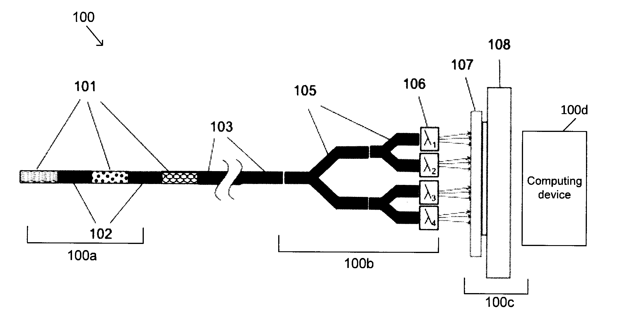
[0005]In one aspect, at least one embodiment described herein provides a radiation dosimeter for measuring radiation dose at multiple points within a detection region. The radiation dosimeter includes a radiation detector comprising a plurality of scintillating elements located within the detection region and configured to generate optical energy in response to irradiation in the detection region, a single collecting light guide optically coupled to the radiation detector and configured to receive and transmit the optical energy generated by the plurality of scintillating elements, a spectral filter stage optically coupled to the single collecting light guide and configured to receive and spectrally decouple the transmitted optical energy, a photo-detector stage optically coupled to the spectral filter stage and configured to generate electrical signals indicative of optical energy within at least one region of the spectrally decoupled optical energy, and a computing device connecte...


PUM


Abstract

Various embodiments are described herein for a radiation dosimetry apparatus and associated methods for measuring radiation dose. In some embodiments, the apparatus includes multiple scintillating elements for detecting amounts of radiation dose at multiple points within a detection region. Each of the scintillating elements generates light in response to radiation interacting within their volume. A light guide combines the light generated by all of the scintillating elements as well as radiation-induced contaminated optical energy and transmits the combined light to a spectral analysis setup. Multi or hyper-spectral calibration technique allows calculating the dose or dose rate at the positions of the different scintillating elements. The calibration technique isolates the light produced by a given scintillating element from the other scintillating elements as well as any other source of radiation-induced contaminating light.

Description

RELATED APPLICATIONS[0001]This application claims the benefit of U.S. Provisional Patent Application No. 61 / 489,639 filed May 24, 2011, the entire contents of which are hereby incorporated by reference herein for all purposes.FIELD[0002]Various embodiments are described herein relating to apparatus and methods for determining radiation doses at multiple points within one or multiple detection regions coupled to a single collecting light guide.INTRODUCTION[0003]Plastic scintillation detectors have been used for dose measurement in radiation therapy due to their advantageous characteristics over other types of radiation detectors. For example, the water equivalence of plastic scintillation detectors allows for their use without perturbation of the radiation field. The scintillating element of plastic scintillation detectors also emits light proportionally to the radiation dose striking it in a nanosecond time-scale allowing for a rapid read-out. The response characteristics of plastic...

Claims


Application Information

Patent Timeline
IPC IPC(8): G01T1/10G01T1/20
CPCG01T1/10G01T1/2006G01T1/2002G01T1/161A61N5/1071G01T1/2008
Inventor THERRIAULT-PROULX, FRANCOISBEAULIEU, LUCARCHAMBAULT, LOUISBEDDAR, SAM
Owner UNIV LAVAL