
Distributed strain and temperature discrimination in polarization maintaining fiber

a technology of polarization maintaining fiber and temperature discrimination, applied in the field of optical measurement, can solve problems such as strain and temperature discrimination, affecting optical fibers, and difficulty in distinguishing between two or more physical characteristics or parameters,

Active Publication Date: 2009-05-26
INTUITIVE SURGICAL OPERATIONS INC
View PDF12 Cites 77 Cited by
  • Summary
  • Abstract
  • Description
  • Claims
  • Application Information

AI Technical Summary

Problems solved by technology

A limitation of the two approaches described above is the difficulty in distinguishing between two or more physical characteristics or parameters, e.g., strain and temperature, affecting an optical fiber.

Method used


Image

  • Distributed strain and temperature discrimination in polarization maintaining fiber
  • Distributed strain and temperature discrimination in polarization maintaining fiber
  • Distributed strain and temperature discrimination in polarization maintaining fiber

Examples


Embodiment Construction

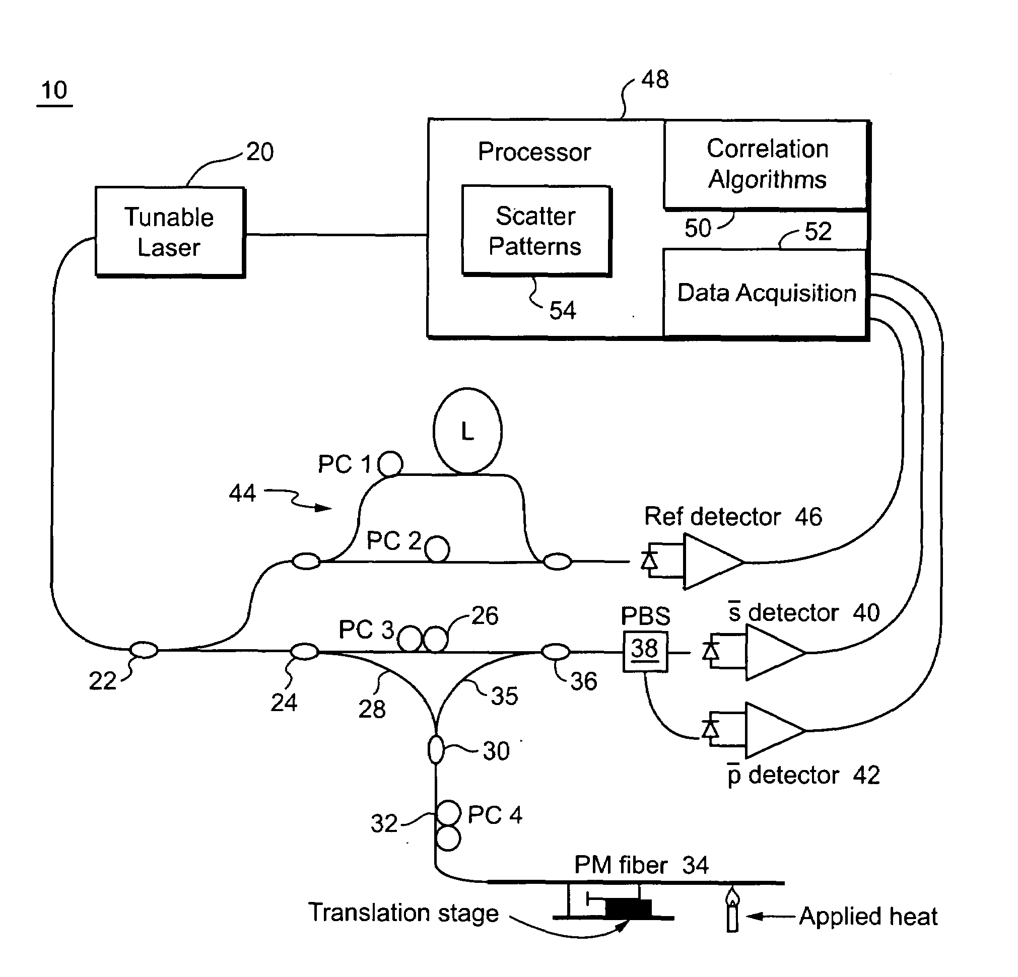
[0040]The following description sets forth specific details, such as particular embodiments, procedures, techniques, etc. for purposes of explanation and not limitation. But it will be appreciated by one skilled in the art that other embodiments may be employed apart from these specific details. Although PM optical fiber is used in the following description, this technology may be applied to any waveguide or optical device with a significant birefringence. In some instances, detailed descriptions of well known methods, interfaces, circuits, and device are omitted so as not obscure the description with unnecessary detail. Moreover, individual blocks are shown in some of the figures. Those skilled in the art will appreciate that the functions of those blocks may be implemented using individual hardware circuits, using software programs and data, in conjunction with a suitably programmed digital microprocessor or general purpose computer, using application specific integrated circuitry...


PUM

PropertyMeasurementUnit
lengthsaaaaaaaaaa
lengthsaaaaaaaaaa
physical characteristicaaaaaaaaaa

Abstract

A portion of a polarization maintaining (PM) optical fiber having two polarization states is analyzed. First and second spectral responses of the PM fiber portion are determined. In a preferred implementation, the spectral responses are determined using Optical Frequency Domain Reflectometry (OFDR). Each polarization state of the PM fiber portion has a corresponding spectral component in the first spectral response. First and second spectral analyses of the PM fiber portion are performed using the first and second spectral responses. Based on those spectral analyses of the PM fiber portion, a first physical characteristic affecting the PM fiber portion is determined that is distinct from a second different physical characteristic affecting the fiber portion. Example physical characteristics include temperature and strain. An output signal related to the first physical characteristics affecting the fiber portion is provided, e.g., for display, further processing, etc.

Description

CLAIM OF BENEFIT OF PROVISIONAL PATENT APPLICATION[0001]Priority is claimed from U.S. Provisional Patent Application No. 60 / 814,088, filed on Jun. 16, 2006. The contents of this provisional application are incorporated by reference.RELATED APPLICATIONS[0002]This application is related to U.S. patent application Ser. No. 11 / 062,740, filed on Jan. 24, 2005, and U.S. patent application Ser. No. 11 / 371,229, filed on Mar. 9, 2006, the contents of which are incorporated by reference.TECHNICAL FIELD[0003]The technical field relates to optical measurements, and more particularly, to advantageous new uses of Optical Frequency Domain Reflectometry (OFDR).BACKGROUND AND SUMMARY[0004]Mixing between a reference signal and a data signal is often necessary to extract information about an optical device or network. A probe signal and a reference signal originating from the same source are typically mixed, resulting in fringes that can be detected and used to assess information about the device bein...

Claims


Application Information

Patent Timeline
Patent Type & Authority Patents(United States)
IPC IPC(8): G01B9/02G01L1/24G01N21/00
CPCG01M11/3172G01K11/32G01L1/242G01D5/35361G01D5/3538
Inventor FROGGATT, MARK E.
Owner INTUITIVE SURGICAL OPERATIONS INC
Learn More