Method and apparatus for determining drill string movement mode

a drill string movement and movement mode technology, applied in the field of drill string movement mode determination, can solve the problems of affecting the wear and tear of the drill string, the movement mode of the drill string within the wellbore which can be quite destructive, and the impact on the drilling performance of the drill string

Inactive Publication Date: 2005-03-31
HUTCHINSON MARK W
View PDF7 Cites 84 Cited by
  • Summary
  • Abstract
  • Description
  • Claims
  • Application Information

AI Technical Summary

Problems solved by technology

The forces acting on a typical drill string during drilling are very large.
Because the typical drill string is composed of threaded pipe segments having diameter on the order of only a few inches, the combination of length of the drill string and the magnitude of the axial and torsional forces acting on the drill string can cause certain movement modes of the drill string within the wellbore which can be quite destructive.
“Lateral” vibrations and “torque shocks” can also be detrimental to drill string wear and drilling performance.
Any or all of these destructive modes of motion, if allowed to continue during drilling, both decrease drilling performance and increase the risk that some component of the drill string will fail.
A limitation to using surface measurements to determine destructive drill string modes is that the drill string is an imperfect communication channel for axial, lateral and / or torsional accelerations which are imparted to the drill string at or near the bottom of the wellbore.
A limitation to using MWD systems known in the art for determining destructive operating modes in a drill string is that the data communication rate of MWD systems is generally limited to a few bits per second.
As a result, MWD systems known in the art do not necessarily make the best use of the mode-related measurements made by the MWD system sensors.

Method used


Image

  • Method and apparatus for determining drill string movement mode
  • Method and apparatus for determining drill string movement mode
  • Method and apparatus for determining drill string movement mode

Examples


Embodiment Construction

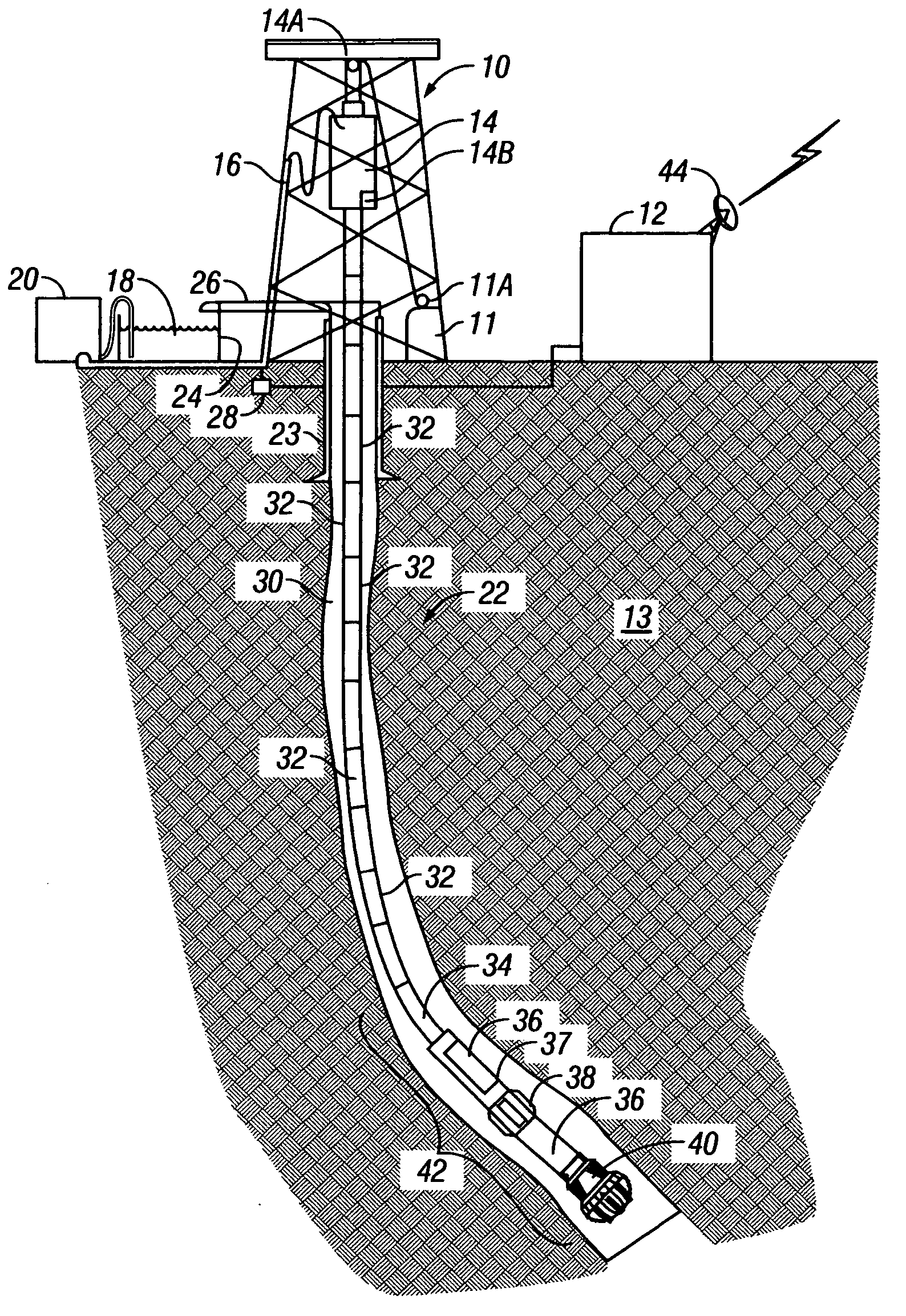
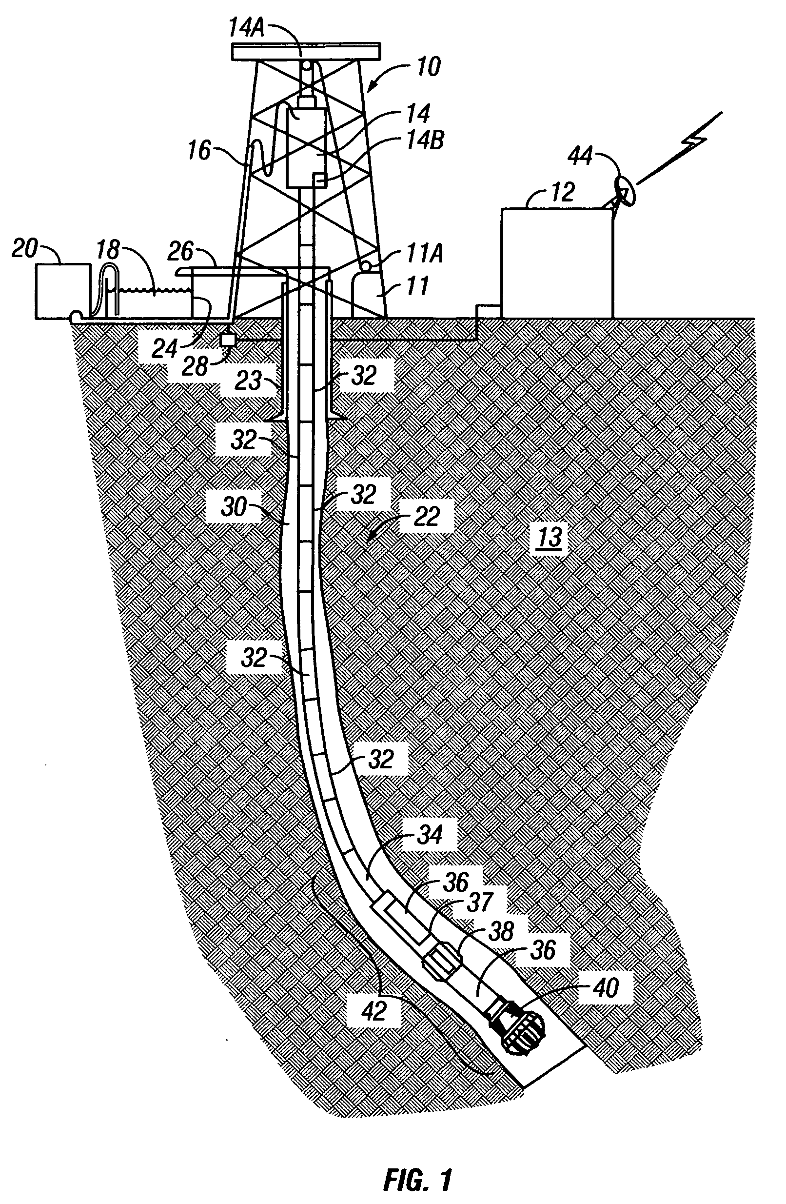
FIG. 1 shows a typical wellbore drilling system which may be used with various embodiments of a method and system according to the invention. A drilling rig 10 includes a drawworks 11 or similar lifting device known in the art to raise, suspend and lower a drill string. The drill string includes a number of threadedly coupled sections of drill pipe, shown generally at 32. A lowermost part of the drill string is known as a bottom hole assembly (BHA) 42, which includes, in the embodiment of FIG. 1, a drill bit 40 to cut through earth formations 13 below the earth's surface. The BHA 42 may include various devices such as heavy weight drill pipe 34, and drill collars 36. The BHA 42 may also include one or more stabilizers 38 that include blades thereon adapted to keep the BHA 42 roughly in the center of the wellbore 22 during drilling. In various embodiments of the invention, one or more of the drill collars 36 may include a measurement while drilling (MWD) sensor and telemetry unit (co...


PUM


Abstract

A method is disclosed for determining movement mode in a drill string. The method includes measuring lateral acceleration of the drill string, determining lateral position of the drill string from the acceleration measurements, and determining mode from the position with respect to time. Also disclosed is a method including measuring drill string acceleration along at least one direction, spectrally analyzing the acceleration, and determining existence of a particular mode from the spectral analysis. Also disclosed is a method for determining destructive torque on a BHA including measuring angular acceleration at at least one location along the BHA, and comparing the acceleration to a selected threshold. The threshold relates to a moment of inertia of components of the BHA and a maximum torque applicable to threaded connections between BHA components. A warning is generated when acceleration exceeds the threshold.

Description

STATEMENT REGARDING FEDERALLY SPONSORED RESEARCH OR DEVELOPMENT Not applicable. BACKGROUND OF INVENTION 1. Field of the Invention The invention relates generally to the field of drilling wellbores through the earth. More particularly, the invention relates to apparatus and methods for determining the dynamic mode of motion of a drill string used to turn a drill bit. 2. Background Art Drilling wellbores through the earth includes “rotary” drilling, in which a drilling rig or similar lifting device suspends a drill string which turns a drill bit located at one end of the drill string. Equipment on the rig and / or an hydraulically operated motor disposed in the drill string rotate the bit. The rig includes lifting equipment which suspends the drill string so as to place a selected axial force (weight on bit—“WOB”) on the drill bit as the bit is rotated. The combined axial force and bit rotation causes the bit to gouge, scrape and / or crush the rocks, thereby drilling a wellbore thro...

Claims


Application Information

Patent Timeline
Patent Type & Authority Applications(United States)
IPC IPC(8): E21B41/00E21B44/00E21B47/04
CPCE21B47/04E21B44/00
Inventor HUTCHINSON, MARK W.
Owner HUTCHINSON MARK W
Why Eureka
Try Eureka