Maintaining
linearity is especially a problem for the power
amplifier (PA)—usually the most power-consumptive part of the system.
Lowering PA average power (“power backoff”) to accommodate the peak powers and avoid
nonlinear distortion also unacceptably diminishes its power efficiency.
Diminished efficiency worsens battery life in handhelds and worsens energy costs and thermal management issues in base stations.
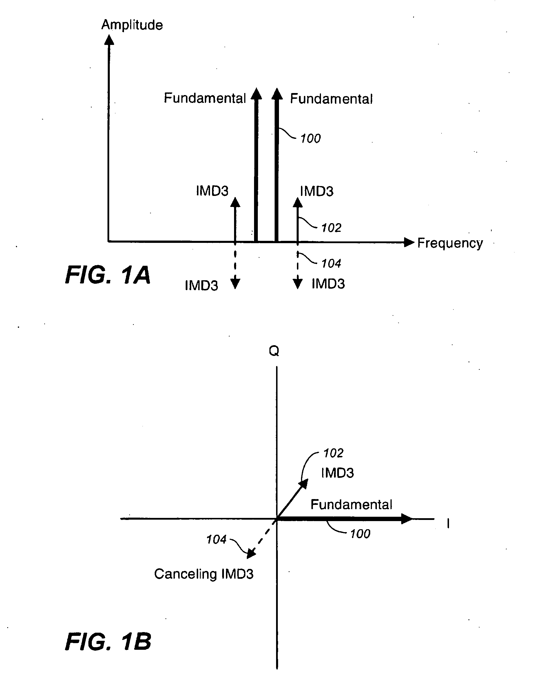
It needs to be noted that simply filtering out undesired
nonlinear distortion products is ineffective as distortion products due to odd-degree nonlinearities manifest both within and very close to the fundamental frequencies.
At RF and
microwave frequencies, however, distortion phase can deviate from fundamental
signal phase by arbitrary angles for many reasons, including reactive and physically remote nonlinearities.
Designing for, and maintaining, the proper magnitude and phase relationships (that is, vector relationships) between distortion products and the ameliorative solution is a difficult aspect of
linearization.
The polar format independently tunes magnitude and phase, but the
phase modulation aspect is in general difficult to implement, especially if
delay lines are used.
The dynamical coordination of the magnitude and phase modulators is also very difficult, especially at the high modulation rates of modern systems.
Further, inexpensive scalar
spectrum analysis provides no indication as to whether magnitude or phase is preferably adjusted while tuning for lowered distortion, and so convergence can be very poor unless expensive vector
spectrum analysis is invoked.
The physically large and mixed-technology aspects of many
linearizer implementations preclude integration, thus increasing cost and environmental sensitivities.
Physically large distributed elements such as
delay lines are not uncommon [see, for example, U.S. Pat. No. 6,788,139, to Villemazet], but are limited to microwave frequencies, and their lengths are very difficult to adjust.
Phase shifters are easier to tune but have the desired
delay only at a single frequency, limiting instantaneous
linearization bandwidth.
Many
linearization implementations also consume high DC power, in direct opposition to the primary engendering motivation.
The diminished power efficiency quickly becomes unacceptable, however.
But limited loop gains and excess phase shifts at such high frequencies forces severe and unacceptable tradeoffs amongst distortion suppression, bandwidth, and stability.
But errors in the feedback path, and in particular the added
noise, delay, and nonlinearities of the downconverter, are not corrected by the loop and add directly to the
signal.
Additionally, sensitivity loop delays remains high on the scale of an RF period so as to make drift and
instability a problem.
The downconverter also adds appreciable cost and complexity to the system.
Adaptive systems are commonly needed to compensate for drift, adding further complexity and expense.
Further, the power drawn by the
error amplifier and the inefficiencies of the RF /
microwave power combiner at the output serve to limit overall available efficiency.
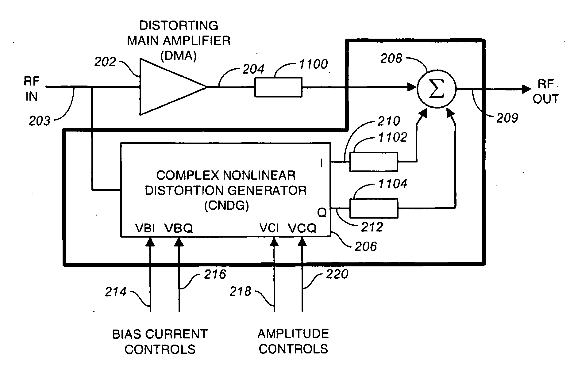
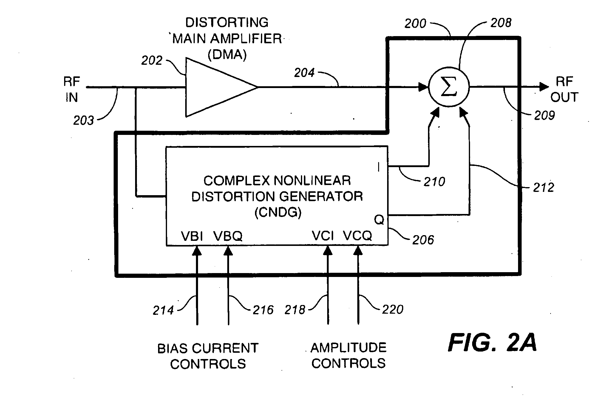
As with feedforward, predistorters are open loop and thus susceptible to drift, either in the
amplifier being linearized (the “distorting main
amplifier”, or DMA) or the linearizer itself.
Predistorters are generally of different physical construction and in less-than-intimate contact with the DMA, exacerbating drift problems.
Another issue with predistorters is that when canceling
lower order distortion products, the
cascade of predistorter plus distorting main amplifier generates new undesired distortion products of orders higher than those of the nonlinearities of either individual block [Steven Cripps, Advanced Techniques in
RF Power Amplifier Design, Artech House, 2002, pg.
Digital predistorters (DPD), on the other hand, operate at
baseband frequencies and must provide
processing power (and thus consume DC power) directly proportional to the
modulation bandwidth—a
disadvantage given the modern trend towards expanding modulation bandwidths.
Further, as systems are driven harder for better power efficiency, they also increase the order of significant distortion products.
Note that these bandwidth and power issues involve not only the DPD but also the digital-to-analog converter (DAC) and the input stages of the upconverter.
The power consumed by the
digital signal processing subsystem in this situation rapidly diminishes overall system power efficiency to a point of diminishing returns.
The UTD sequence is relatively rare because of difficulties of
signal processing at the very high second
harmonic frequencies and because the load second
harmonic impedance is often engineered to be short for efficiency reasons [Cripps].
Lacking vector tunability however, this scalar approach provides only partial linearization and relies on the short
time delays relative to a RF period achieved with tight on-
chip integration.
Disadvantages of DTU OOB COM systems are susceptibility to
noise in the RF input envelope detection process and the vagaries of
low frequency circuits such as bandwidth limitations and 1 / f
noise.
Derivative superposition addresses
transfer function nonlinearities but does not address the products of the nonlinear output current divide ratio between the nonlinear part of the FET's output
admittance and the load.
An auxiliary FET bias adjustment, in essence a scalar tuning control, cannot provide compensation.
Unfortunately the
design analysis equations are very complicated, even when considering only a subset of FET and circuit properties.
The tapped
inductor is also a difficult and physically large design.
Further, the design works at only one
center frequency and is thus not amenable to multi-band radios.
The lack of vector tunability, the intractably difficult analysis, and the insufficiently accurate
simulation models for very high levels of distortion suppression mean the design is substantially empirical, requiring several iterations.
Even then, process variations limit the statistically available
linearity [Ganesan, et. al., “A Highly Linear Low-
Noise Amplifier”, IEEE Trans.
Like derivative superposition, the integrated linearizers of Garuts, Kim et al, and Otaka suffer a difficult
design process and high sensitivity to process variations.
Linearizers with local RF
negative feedback suffer other problems mentioned previously.

