Low Frequency Response Microphone Diaphragm Structures And Methods For Producing The Same

a diaphragm and microphone technology, applied in the field of microphones, can solve the problems of reducing the sensitivity of the microphone, limited low frequency response of the microphone, and the ability of the microphone's fabrication process to make very small slots

Active Publication Date: 2014-09-18
INVENSENSE
View PDF3 Cites 31 Cited by
  • Summary
  • Abstract
  • Description
  • Claims
  • Application Information

AI Technical Summary

Benefits of technology

[0007]Some embodiments have an equalization aperture to allow equalization of ambient (or static) pressure on the top and bottom of the diaphragm. An equalization aperture may have a variety of shapes and cross-sections, depending on the desired acoustic resistance. For example, in some embodiments the sealing layer further includes an equalization aperture configured to allow air flow from the top side of the diaphragm to the bottom side of the diaphragm, the equalization aperture having a cross-section in the plane of the diaphragm of not greater than 20 square micrometers. In some embodiments, the equalization aperture is disposed adjacent the spring gap, such air may flow from the top side of the diaphragm to the bottom side of the diaphragm through the spring gap. In other embodiments, the diaphragm includes a diaphragm aperture extending from the top side of the diaphragm to the bottom side of the diaphragm; and the equalization aperture is aligned with the diaphragm aperture, such that air may flow from the top side of the diaphragm to the bottom side of the diaphragm through the diaphragm aperture.

Problems solved by technology

Indeed, if their impedance is too small, most of the air flows through them and only a fraction of the acoustic energy in the air is imparted to the diaphragm to make the diaphragm move, thereby reducing the sensitivity of the microphone.
So the low frequency response of the microphone is limited by the design of the spring channel slot geometry.
As such, the acoustic performance of prior art MEMS microphones is determined, in part, by limits on the ability of the microphone's fabrication process to make very small slots.

Method used


Image

  • Low Frequency Response Microphone Diaphragm Structures And Methods For Producing The Same
  • Low Frequency Response Microphone Diaphragm Structures And Methods For Producing The Same
  • Low Frequency Response Microphone Diaphragm Structures And Methods For Producing The Same

Examples


first embodiment

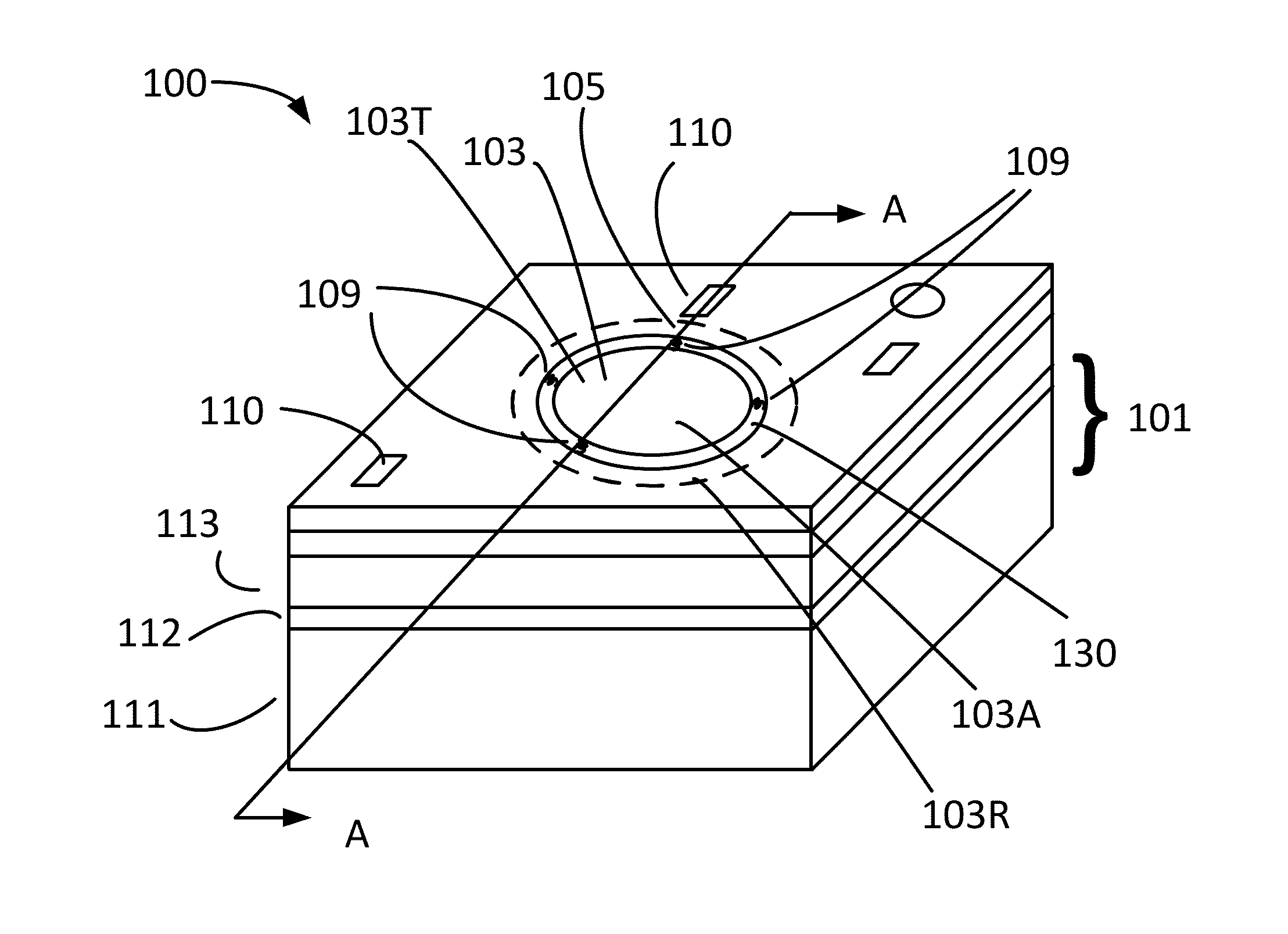
[0006]In a first embodiment, a MEMS microphone includes a substrate having a plurality of diaphragm suspension points; a backplate; a diaphragm having a top side and an opposing bottom side, the diaphragm defining a diaphragm plane, the diaphragm separated from the plurality of diaphragm suspension points by a spring gap in the diaphragm plane; a plurality of springs within the diaphragm plane and within the spring gap, each of the plurality of springs coupled to the diaphragm and to a corresponding one of the plurality of diaphragm suspension points, such that the diaphragm is movably suspended from the plurality of diaphragm suspension points when the microphone is in operation, and such that the diaphragm is spaced from the backplate by a variable diaphragm gap; and a sealing layer laminated on the diaphragm and spanning the spring gap, wherein the backplate and diaphragm form a variable capacitor of a microphone.

[0007]Some embodiments have an equalization aperture to allow equal...

embodiment 200

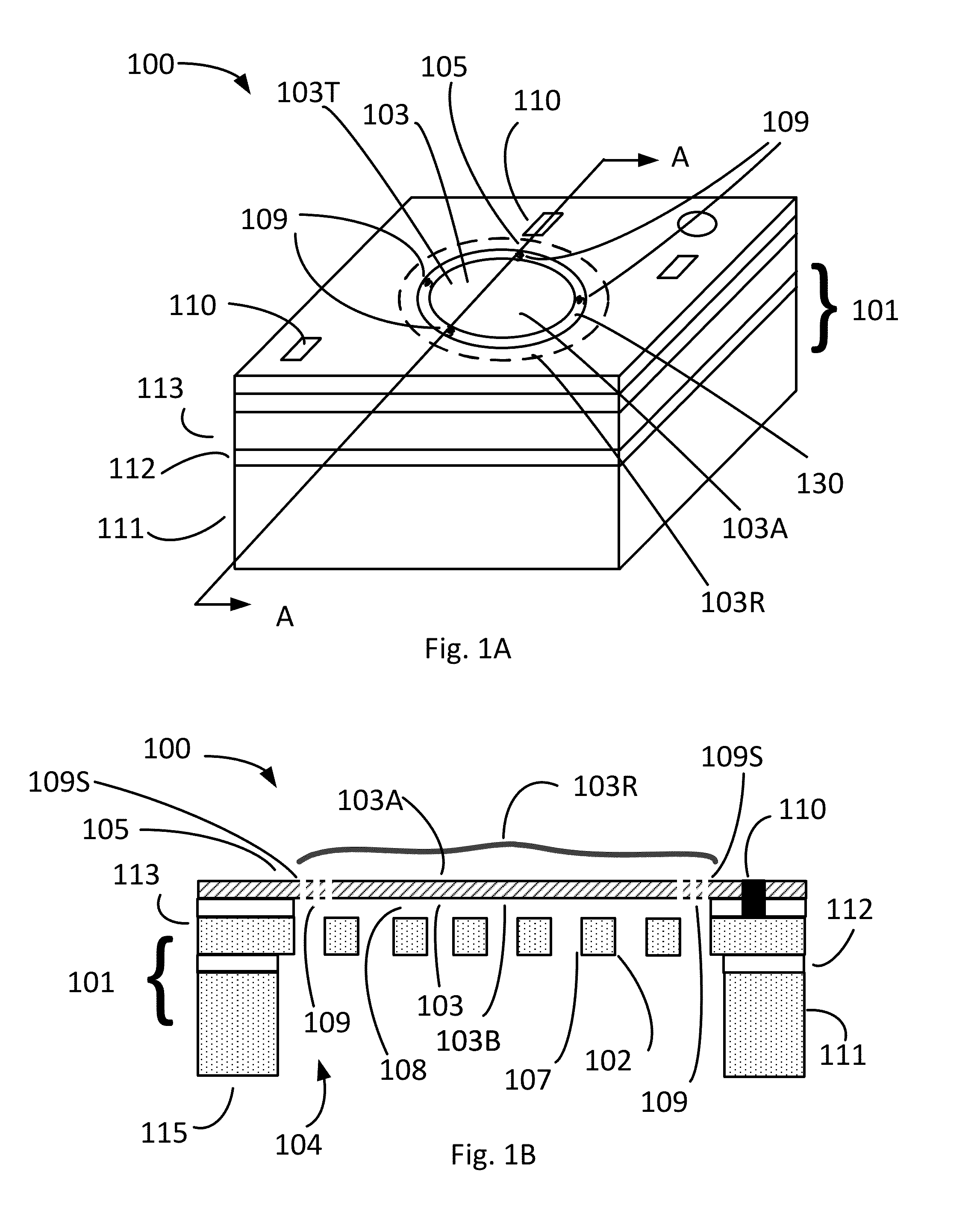
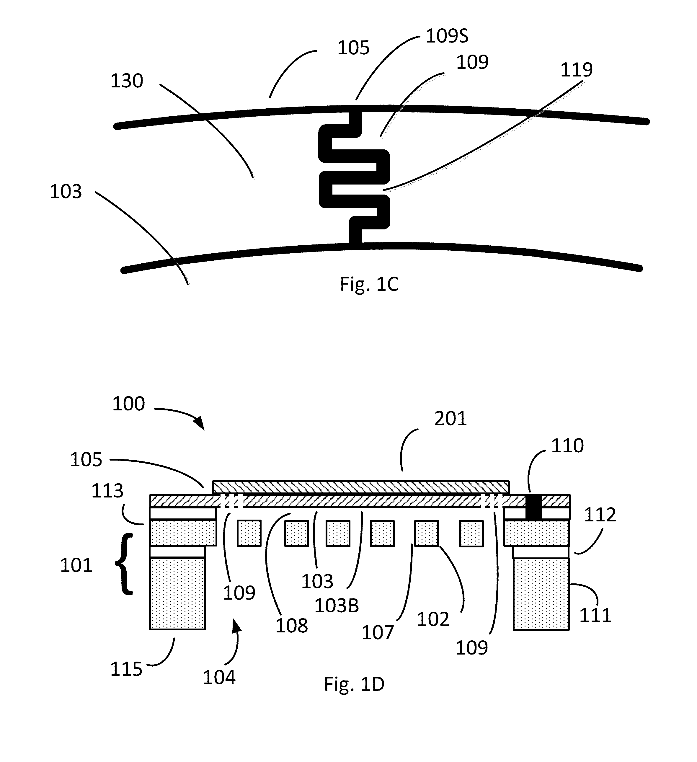
[0047]In the embodiment 200 of FIG. 2A, the sealing layer 201 includes a sealing layer aperture 210 and the diaphragm 103 includes a diaphragm aperture 211 aligned with the sealing layer aperture 210. As used herein, the sealing layer aperture 210 and the diaphragm aperture 211 are aligned to form an equalization aperture 213, such that air can pass completely through the diaphragm 103 by passing through the sealing layer aperture 210 and the diaphragm aperture 211. In other words, the aperture 210 and the diaphragm aperture 211 are in fluid communication with each other. As such, the sealing layer aperture 210 and the diaphragm aperture 211 form a small equalization aperture 213 by which air pressure on the opposing faces of the diaphragm (top diaphragm face 103T and bottom diaphragm face 103B) can equalize.

[0048]Although the microphone 200 includes an equalization aperture 213, other embodiments (e.g., microphone 100 in FIG. 1B) may not have such equalization apertures. For exampl...

embodiment 230

[0052]In addition, the equalization aperture 213 may be located in a variety of locations. Indeed, in the embodiment 230 of FIG. 2B, the equalization aperture 213 passes through the sealing layer at the spring gap, so that air may pass through the equalization aperture 213 in the sealing layer and through the spring gap, without passing through an aperture in the diaphragm.

[0053]Another embodiment of a MEMS microphone 250 is schematically illustrated in FIG. 2C, in which the diaphragm 103 is suspended from diaphragm suspension points 109S by springs 109, and the backplate 102 is supported above the substrate 251. In microphone 250, the equalization aperture 213 is in the diaphragm, similar to the equalization aperture in microphone 200 in FIG. 2A. The substrate 251 may be a silicon-on-insulator wafer, or may by a different substrate on which various layers are disposed in the construction of the microphone 250.

[0054]Another embodiment of a MEMS microphone 270 is schematically illust...


PUM

PropertyMeasurementUnit
thicknessaaaaaaaaaa
widthaaaaaaaaaa
radiusaaaaaaaaaa

Abstract

A microphone system includes a diaphragm suspended by springs and including a sealing layer that seals passageways which, if left open, would degrade the microphone's frequency response by allowing air to pass from one side of the diaphragm to the other when the diaphragm is responding to an incident acoustic signal. In some embodiments, the sealing layer may include an equalization aperture to allow pressure to equalize on both sides of the diaphragm.

Description

TECHNICAL FIELD[0001]The present invention relates to microphones, and more particularly to diaphragm structures for MEMS microphones.BACKGROUND ART[0002]A MEMS microphone measures the instantaneous differential pressure between opposing sides of diaphragm. To sense an acoustic wave impinging on a diaphragm, the static pressure on both sides of the moving diaphragm should, ideally, be the same.[0003]In a typical MEMS microphone, springs suspending the diaphragm are patterned in a slot adjacent to the diaphragm (e.g., a gap between the diaphragm and a support structure surrounding the diaphragm), and configured to have the desired spring constant. Portions of the slot not occupied by the patterned springs inherently provide air leakage channels, which allow ambient air to balance the pressure of the diaphragm at both sides. Such channels represent an acoustic short circuit. Indeed, if their impedance is too small, most of the air flows through them and only a fraction of the acoustic...

Claims


Application Information

Patent Timeline
Patent Type & Authority Applications(United States)
IPC IPC(8): B81B3/00B81C1/00
CPCB81C1/00682B81B3/0078B81C1/00158B81B2201/0257B81C1/00523
Inventor LIU, FANGYANG, KUANG L.
Owner INVENSENSE
Why Eureka
Try Eureka