Heterogeneous Energy Storage System and Associated Methods

Inactive Publication Date: 2014-09-18
MANITOBA HYDRO INT
View PDF4 Cites 62 Cited by
  • Summary
  • Abstract
  • Description
  • Claims
  • Application Information

AI Technical Summary

Benefits of technology

[0059]For instance, at any given time, depending on the then-current demand of the load (and then-projected demand of the load going forward), the objective a system operator may be to minimize the cost of generation/supply by the at least one power source in supplying the then-current load and then-projected load going forward by optimally mixing-in power available from the energy storage system at these times. This facet can be particularly significant, and the value provided by the energy storage system can be particularly pronounced, if any of

Problems solved by technology

It is well known that when a number of batteries are connected and arranged in a parallel configuration, having a “weak” cell in the mix can dramatically reduces the total load capability of the battery bank.
Furthermore, a faulty cell would drain energy from the other cells, thereby causing electrical short.
Although a minor electrical short can just result in a faster self-discharge, hence reduced runtime and utility of the battery bank, a more major electrical short can become a fire hazard causing explosion and serious damage.
In light of the foregoing, none of the prior art to date teach a single energy storage system that can accommodate different batteries with different voltage and charge ratings, different designs, different chemistries, different age, and especially, different health statuses with different residual runtimes and capacities.
Conversely, the “health” (hence performance) of a battery deteriorates during its service life due to irreversible physical and chemical changes which take place with usage until eventually the battery is no longe

Method used


Image

  • Heterogeneous Energy Storage System and Associated Methods
  • Heterogeneous Energy Storage System and Associated Methods
  • Heterogeneous Energy Storage System and Associated Methods

Examples


Example

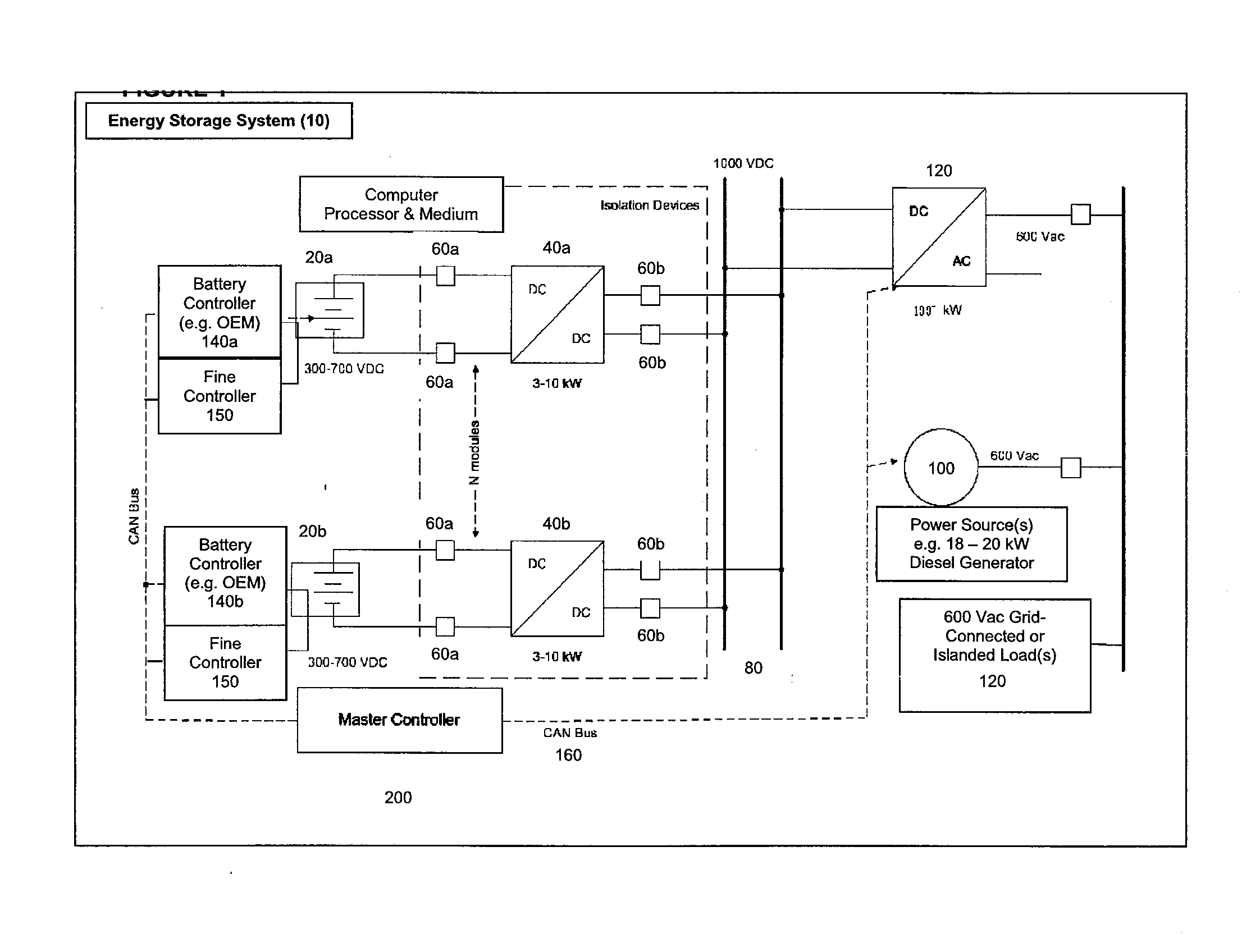
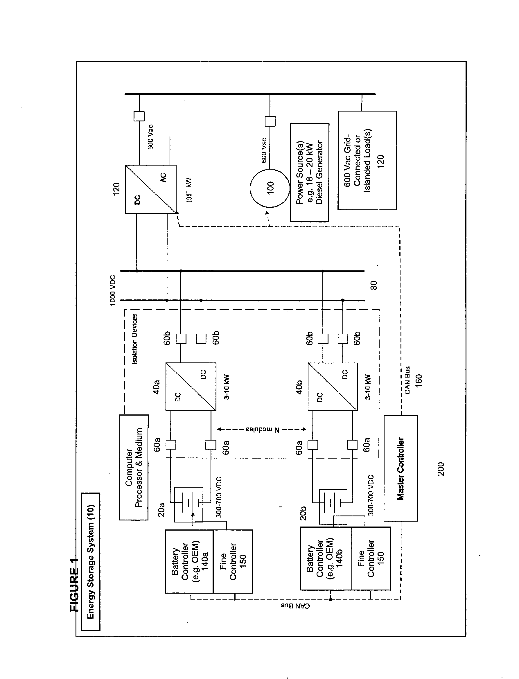
[0077]Referring to the accompanying drawings there is illustrated the fundamental system and methods of the present invention for an improved management and operation of electricity storage systems involving multiple electricity storage units of heterogeneous states of health.

[0078]FIG. 1 is a simple diagrammatic illustration of an example of the novel energy storage system 10, which may be a 150 kWhr-rated system. In a basic example of the system, a plurality of batteries (two of which are exemplified as 20a and 20b) is provided in each module. Each module itself can comprise of multiple batteries connected in series, but it should be noted that a module can simply contain a single battery, or it can comprise multiple batteries connected in parallel as well as in series, depending on the desired capacity (e.g. voltage and current) rating of the module. For the present illustration, the rating of each module is 300-700 VDC.

[0079]The number (N) of modules included in the system would...


PUM


Abstract

A power supply system between a power supply and an electrical load uses a plurality of battery modules which may be different in configuration from one another. The system assesses one or more state variables for each battery module to indicate a health status of the battery module. The variable indicative of the health status typically includes: i) a residual ability of the battery module to accept electric charge, ii) a residual capacity of the battery module to hold electric charge, iii) an internal resistance of the battery module, iv) a conductance of the battery module, v) a capacitance of the battery module, vi) a rate of charge of the battery module, vii) a rate of discharge of the battery module under load, or viii) a rate of self-discharge of the battery module. The system then generates unique charging and discharging criteria for each battery module which is specifically derived from the health status of the battery module.

Description

[0001]This application claims the benefit under 35 U.S.C. 119(e) of U.S. provisional application Ser. No. 61 / 778,938, filed Mar. 13, 2013.FIELD OF INVENTION[0002]The present invention relates in general to novel method and system for management and operation of electricity storage systems involving heterogeneous electricity storage units.BACKGROUND OF THE INVENTION[0003]With increasing adoption of electronic devices and vehicles, significant investments have been made in developing battery technologies to drive down costs, achieve greater energy densities, and smaller battery sizes. For example, lithium-ion batteries today represent a ten-fold drop in installed costs when compared to conventional redox flow systems.[0004]Further, the continuing improvements and increasing prevalence of electric vehicles (whether hybrid electric or plug-in electric) in society, repurposing and using used batteries from these vehicles after their factory operational lifespan may also be viable for ele...

Claims


Application Information

Patent Timeline
IPC IPC(8): H02J7/00H01M10/44
CPCH01M10/441H02J7/0068H01M10/482H02J7/00036H02J7/00047Y02E60/10H02J7/0013
Inventor WACHAL, RANDY W.
Owner MANITOBA HYDRO INT
Why Eureka
Try Eureka