Compact wideband patch antenna

a patch antenna and wideband technology, applied in the field of patch antennas, can solve the problems of patch antennas not being able to communicate with such a gnss satellite constellation, patch antennas being too narrow to overlap the frequency band of a second gnss, and not being able to communicate with the second gnss satelli

Active Publication Date: 2014-09-18
TE CONNECTIVITY CORP
View PDF5 Cites 18 Cited by
  • Summary
  • Abstract
  • Description
  • Claims
  • Application Information

AI Technical Summary

Problems solved by technology

The patch antenna therefore cannot communicate with such a GNSS satellite constellation because the patch antenna does not operate within the frequency band of the GNSS satellite constellation.
But, the frequency band of the patch antenna may be too narrow to overlap the frequency band of a second GNSS satellite constellation that serves a different region.
Accordingly, the patch antenna is c

Method used


Image

  • Compact wideband patch antenna
  • Compact wideband patch antenna
  • Compact wideband patch antenna

Examples


Embodiment Construction

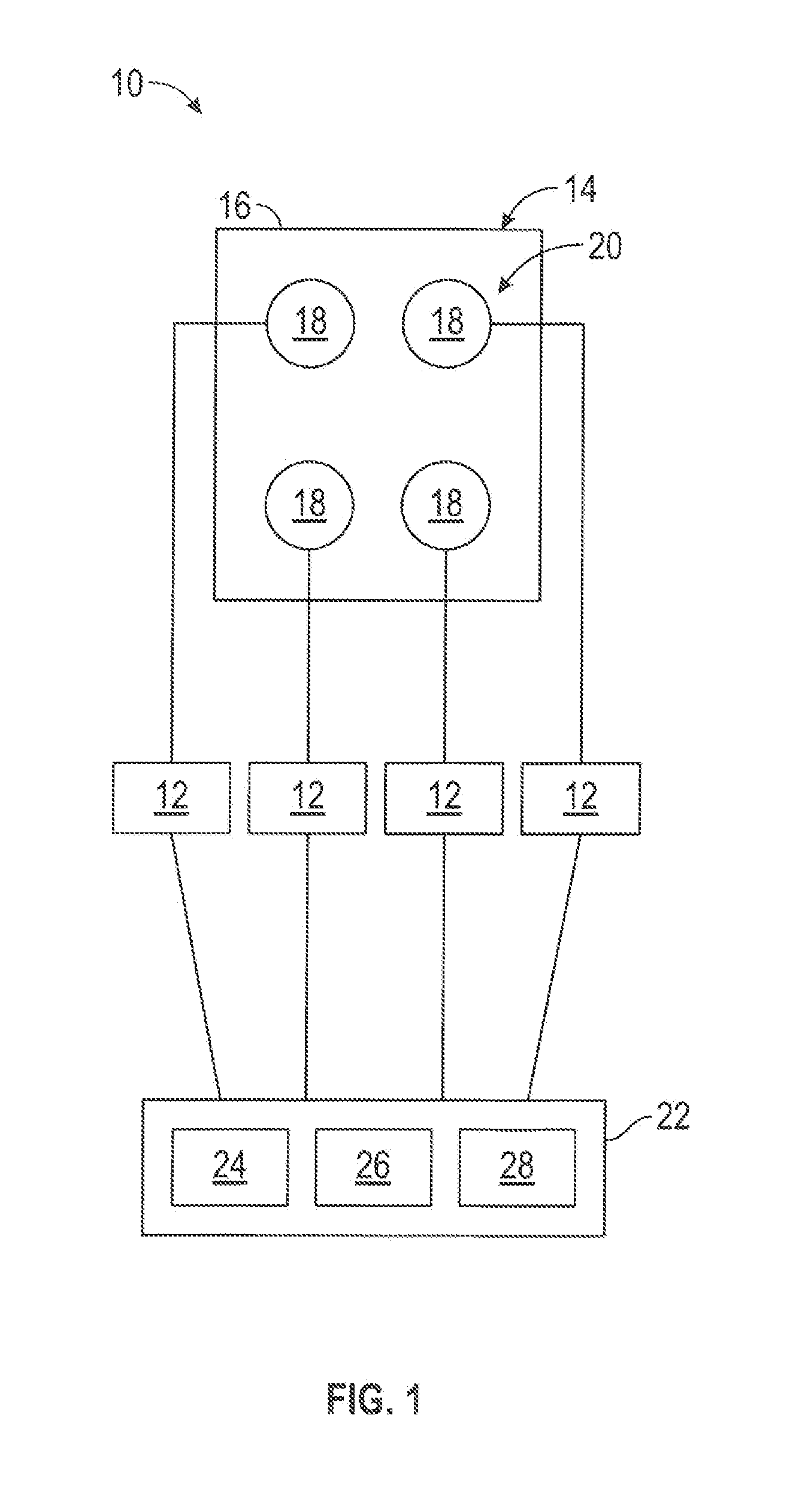
[0019]FIG. 1 is a schematic diagram of an exemplary embodiment of an antenna system 10. The antenna system 10 includes a plurality of feed networks 12 and an antenna assembly 14. The antenna assembly 14 includes a ground plane 16 and one or more patch antennas 18 positioned on the ground plane 16. In the exemplary embodiment of the antenna system 10, the antenna assembly 14 includes an array 20 of four patch antennas 18. But, the array 20 may include any number of patch antennas 18, the antenna assembly 14 may include any number of the arrays 20, and the antenna assembly 14 may include any number of patch antennas 18 overall. In some embodiments, the antenna assembly 14 includes only a single patch antenna 18. The patch antennas 18 may be arranged within the array 20 in any other pattern than is shown in FIG. 1.

[0020]The antenna system 10 may function as a transmitting antenna system that transmits RF waves into the environment (e.g., the atmosphere) of the antenna system 10, as a r...


PUM


Abstract

A patch antenna includes a dielectric substrate having a body that extends a thickness from a first side to a second side that is opposite the first side. The body of the substrate includes thru openings that extend through the thickness of the body. A radiating patch is positioned on the first side of the body of the substrate. The radiating patch includes holes that are aligned with corresponding thru openings of the body of the substrate. A ground plane is positioned on the second side of the body of the substrate. At least three feed probes are electromagnetically coupled to the radiating patch such that the patch antenna is configured to generate a circularly polarized radiation pattern. Each feed probe includes a conductive path that extends within a corresponding thru opening of the body of the substrate from the second side of the body to the first side of the body. Each conductive path being exposed along the first side of the body via the holes of the radiating patch. The feed probes are positioned relative to the body of the substrate such that adjacent feed probes are spaced apart from each other along the body. The feed probes are configured to feed the radiating patch at at least three points with approximately equal power amplitude.

Description

BACKGROUND OF THE INVENTION[0001]The subject matter disclosed herein relates generally to antennas, and more particularly to patch antennas.[0002]Satellite navigation systems are well known for providing autonomous geo-spatial positioning. Satellite navigation systems typically include a constellation of satellites that orbit the earth. The constellation of satellites enables an electronic receiver to determine its location (e.g., longitude, latitude, and altitude) using signals that are transmitted by radio frequency (RF) waves from the orbiting satellites. Satellite navigation systems with global coverage are commonly referred to as global navigation satellite systems (GNSSs). Although GNSSs have global coverage, different GNSSs may serve different regions. For example, different GNSSs may serve the United States, Europe, and Russia. Each different GNSS includes its own constellation of satellites that operates within its own frequency bands. In other words, different GNSSs that s...

Claims


Application Information

Patent Timeline
IPC IPC(8): H01Q1/50H01Q1/38
CPCH01Q1/38H01Q1/50H01Q9/045
Inventor FASENFEST, KATHLEEN
Owner TE CONNECTIVITY CORP
Why Eureka
Try Eureka