Compact lens system and array

Active Publication Date: 2014-09-18
THE RGT OF THE UNIV OF MICHIGAN
View PDF1 Cites 28 Cited by
  • Summary
  • Abstract
  • Description
  • Claims
  • Application Information

AI Technical Summary

Benefits of technology

[0077]The significance of having a low cost high resolution imaging system, such as compact lens system 10, which can match the resolution of very expensive bulky microscopes and accuracy of flow cytometers for counting cells, cannot be under stated. The present teachings can be used in low resource settings as well as point of care with very low cost. The present teachings permit one to count red blood cells, white blood cells, identify abnormalities in the blood cells (sickle cell anemia, malaria etc.) instantly. In addition to the diagnostic applications, the present teachings can also be revolutionary in education and research. It will be a revolutionary instrument in research and educational laboratories. A compact system which can provide optical resolution down to the theoretical resolution limit and do it in a package even individual students can afford.
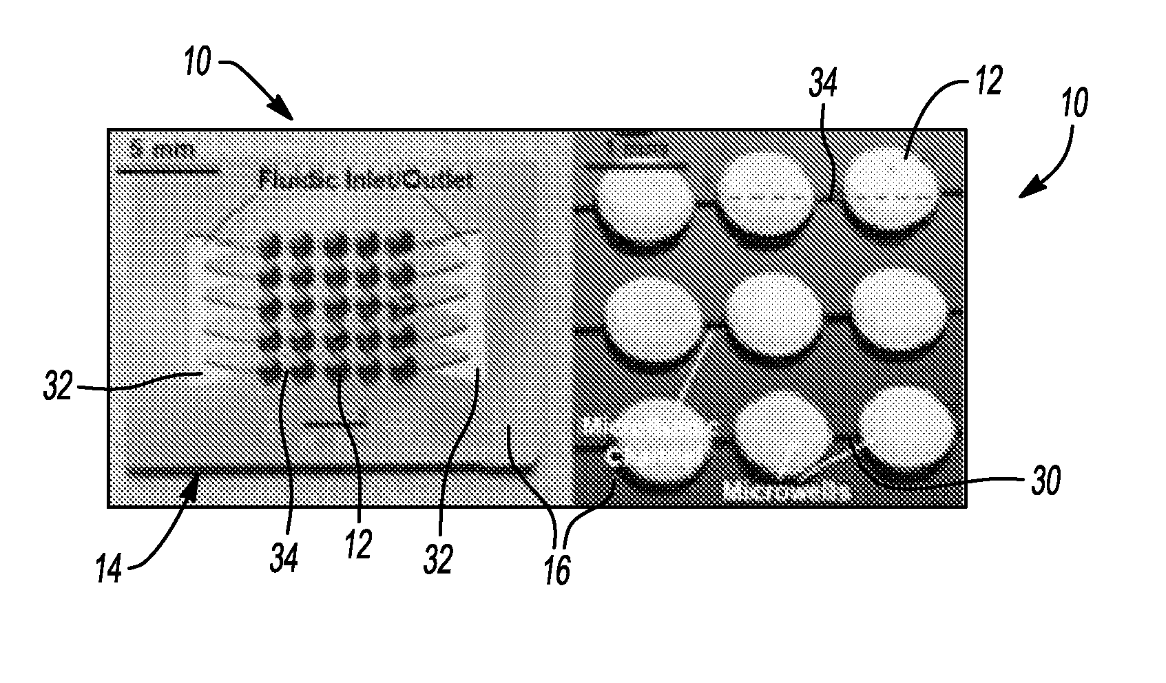
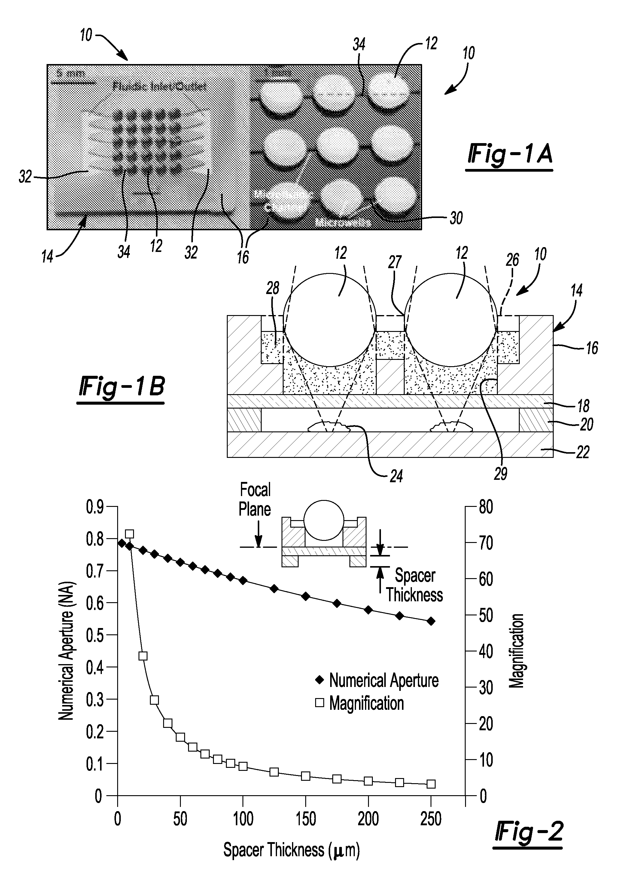
[0078]The present teachings provide a simple optical system consisting of spherical sapphire ball lenses placed on top of an array of index matching oil filled lens wells microfabricated on a silicon chip. In this configuration, the ball lenses

Problems solved by technology

High-end optical systems that achieve submicron resolution imaging rely on multi-element objective lenses that are expensive and bulky.
This is normally achieved by employing expensive high magnification immersion objectives for the microscopes, which can cost several thousand dollars each.
The large physical size of many microscopes is an impediment to making measurements in controlled environments, such as incubators or with living laboratory ani

Method used


Image

  • Compact lens system and array
  • Compact lens system and array
  • Compact lens system and array

Examples


Example

[0043]Corresponding reference numerals indicate corresponding parts throughout the several views of the drawings.

DETAILED DESCRIPTION

[0044]Example embodiments will now be described more fully with reference to the accompanying drawings. Example embodiments are provided so that this disclosure will be thorough, and will fully convey the scope to those who are skilled in the art. Numerous specific details are set forth such as examples of specific components, devices, and methods, to provide a thorough understanding of embodiments of the present disclosure. It will be apparent to those skilled in the art that specific details need not be employed, that example embodiments may be embodied in many different forms and that neither should be construed to limit the scope of the disclosure. In some example embodiments, well-known processes, well-known device structures, and well-known technologies are not described in detail.

[0045]The terminology used herein is for the purpose of describing...


PUM


Abstract

A compact lens system for imaging a sample comprising a substrate having a well formed therein. Index matching material is disposed in the well and a lens member is further disposed in the well in optical contact with the index matching material disposed in the well. A spacer member extends from at least one of the substrate and the lower transparent member to define a spacing from a focal point of the lens member, wherein the lens member and index matching material cooperate to image a sample disposed below the lower transparent member.

Description

CROSS-REFERENCE TO RELATED APPLICATIONS[0001]This application claims the benefit of U.S. Provisional Application No. 61 / 781,944, filed on Mar. 14, 2013. The entire disclosure of the above application is incorporated herein by reference.GOVERNMENT INTEREST[0002]This invention was made with government support under OD006458 awarded by the National Institutes of Health. The government has certain rights in the invention.FIELD[0003]The present disclosure relates generally to imaging and, more particularly, relates to submicron resolution imaging of bacteria, cells, microorganisms, whole tissue, and the like in bright field, dark field and fluorescent image modes in multiple locations simultaneously using a compact lens system and array.BACKGROUND AND SUMMARY[0004]This section provides background information related to the present disclosure which is not necessarily prior art. This section also provides a general summary of the disclosure, and is not a comprehensive disclosure of its ful...

Claims


Application Information

Patent Timeline
IPC IPC(8): G02B21/00
CPCG02B21/00G01N21/6458G01N2201/0639G02B3/0056G02B7/027G02B21/365G01N15/1436
Inventor GULARI, MAYURACHAT NINGGHANNAD-REZAIE, MOSTAFATRIPATHI, ANURAGCHRONIS, NIKOLAOS
Owner THE RGT OF THE UNIV OF MICHIGAN
Why Eureka
Try Eureka