
Non-volatile memory device and programming method

a memory device and non-volatile technology, applied in static storage, digital storage, instruments, etc., can solve the problems of increasing the time required to program (i.e., the “programming period”) of the mlc, and the pre-equalization programming technique tends to drive up the number of verification voltages that must be used during program verification operations, so as to reduce the (or minimize) the programming period and reduce the bit error ra

Active Publication Date: 2014-09-18
SAMSUNG ELECTRONICS CO LTD
View PDF2 Cites 24 Cited by
  • Summary
  • Abstract
  • Description
  • Claims
  • Application Information

AI Technical Summary

Benefits of technology

The patent describes a type of memory that can be programmed faster and with fewer errors. This is achieved by using a special method that reduces the time it takes to program the memory and the likelihood of errors when retrieving data from the memory cells.

Problems solved by technology

However, while this approach is effective in providing increased data density, there are challenges involved in the programming of MLC.
However, the use of more programming steps to avoid coupling effects, increases the time required to program (i.e., the “programming period”) the MLC.
Nonetheless, while certain conventional ISPP methods may be improved in their application by the use of pre-equalization programming techniques, the use of such pre-equalization programming techniques tends to drive up the number of verification voltages that must be used during program verification operations.
This increased number of verification voltages and their application during program verification operations also inevitably increases the programming period associated with a programming operation.

Method used


Image

  • Non-volatile memory device and programming method
  • Non-volatile memory device and programming method
  • Non-volatile memory device and programming method

Examples


Embodiment Construction

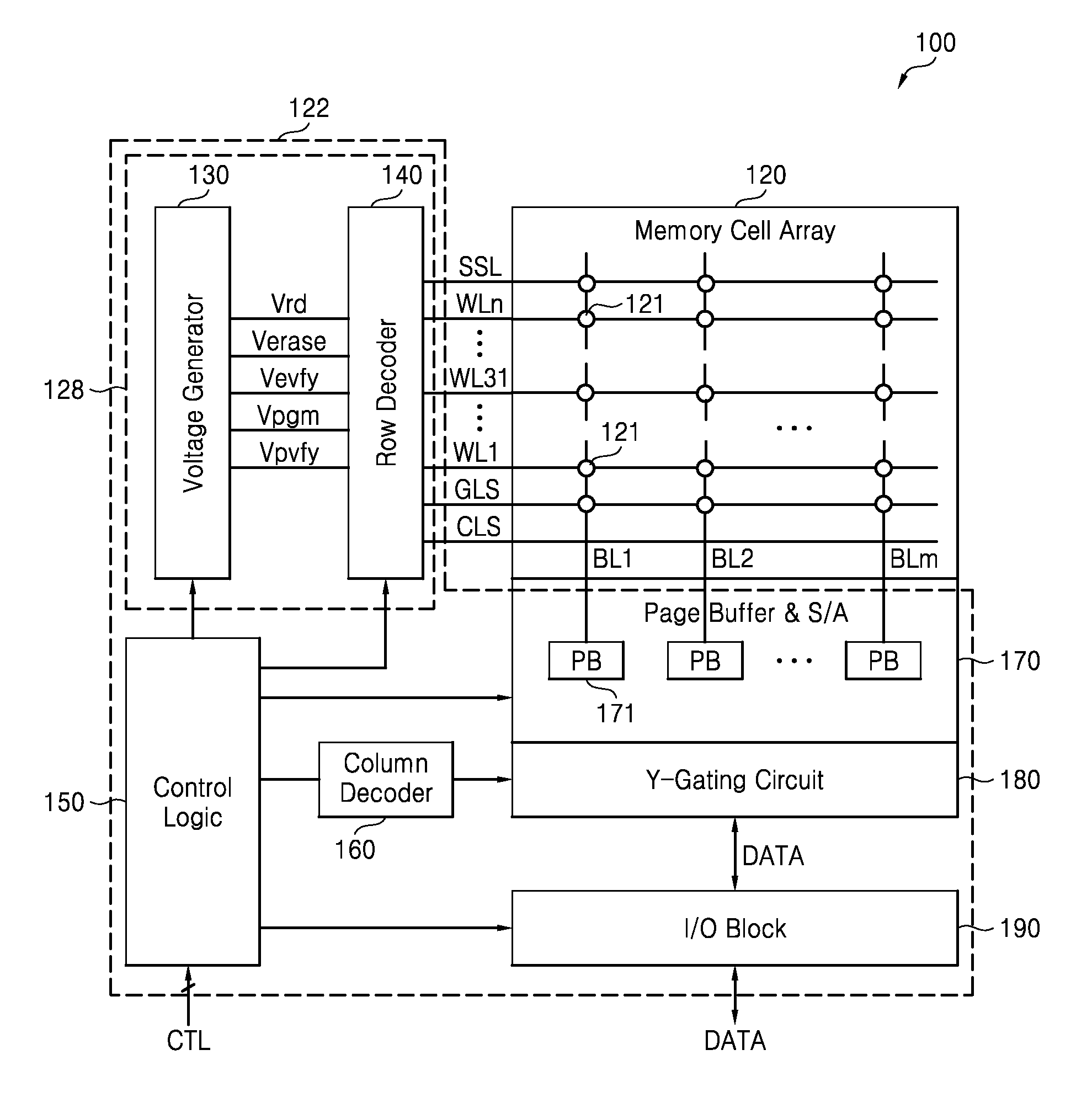
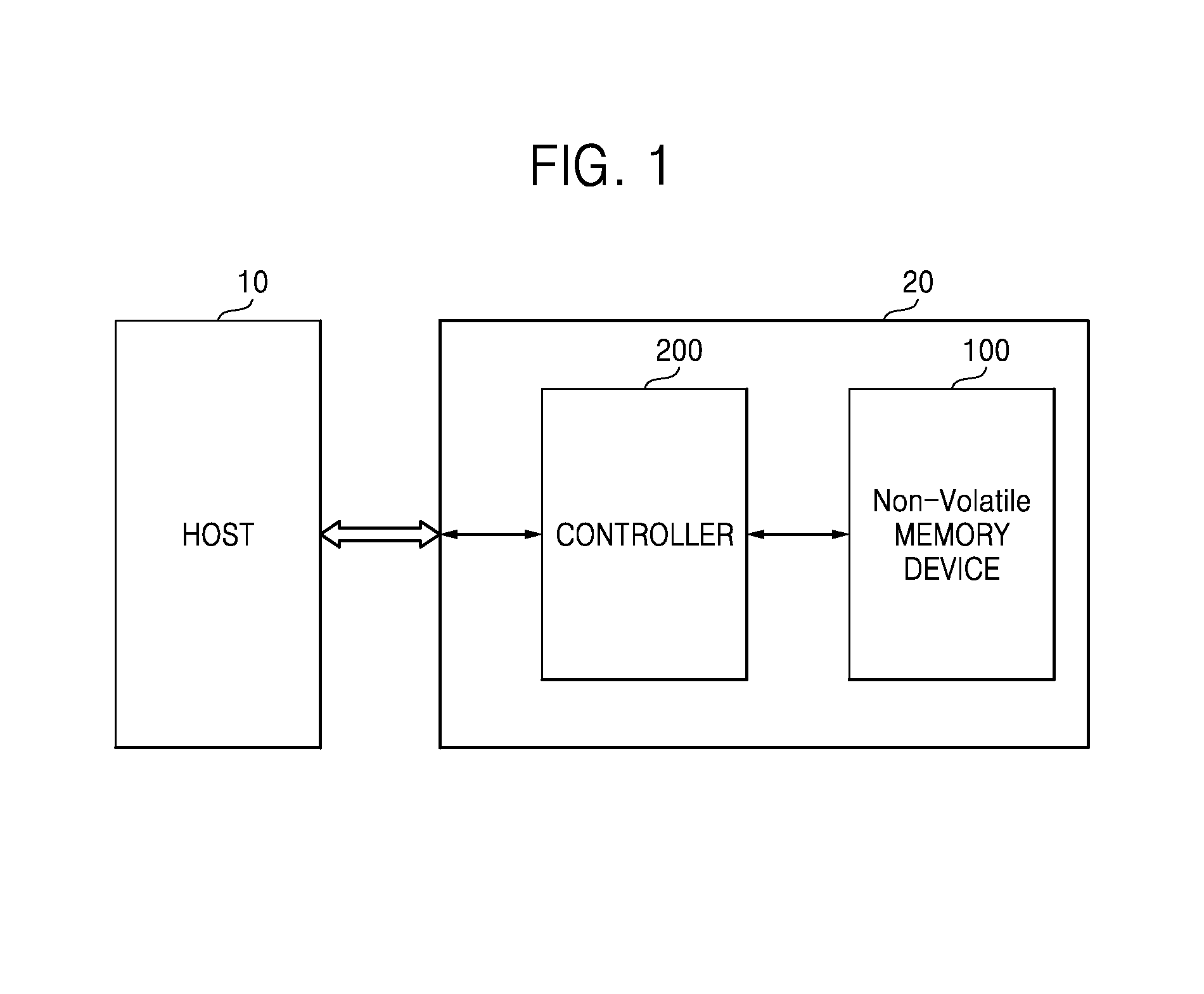
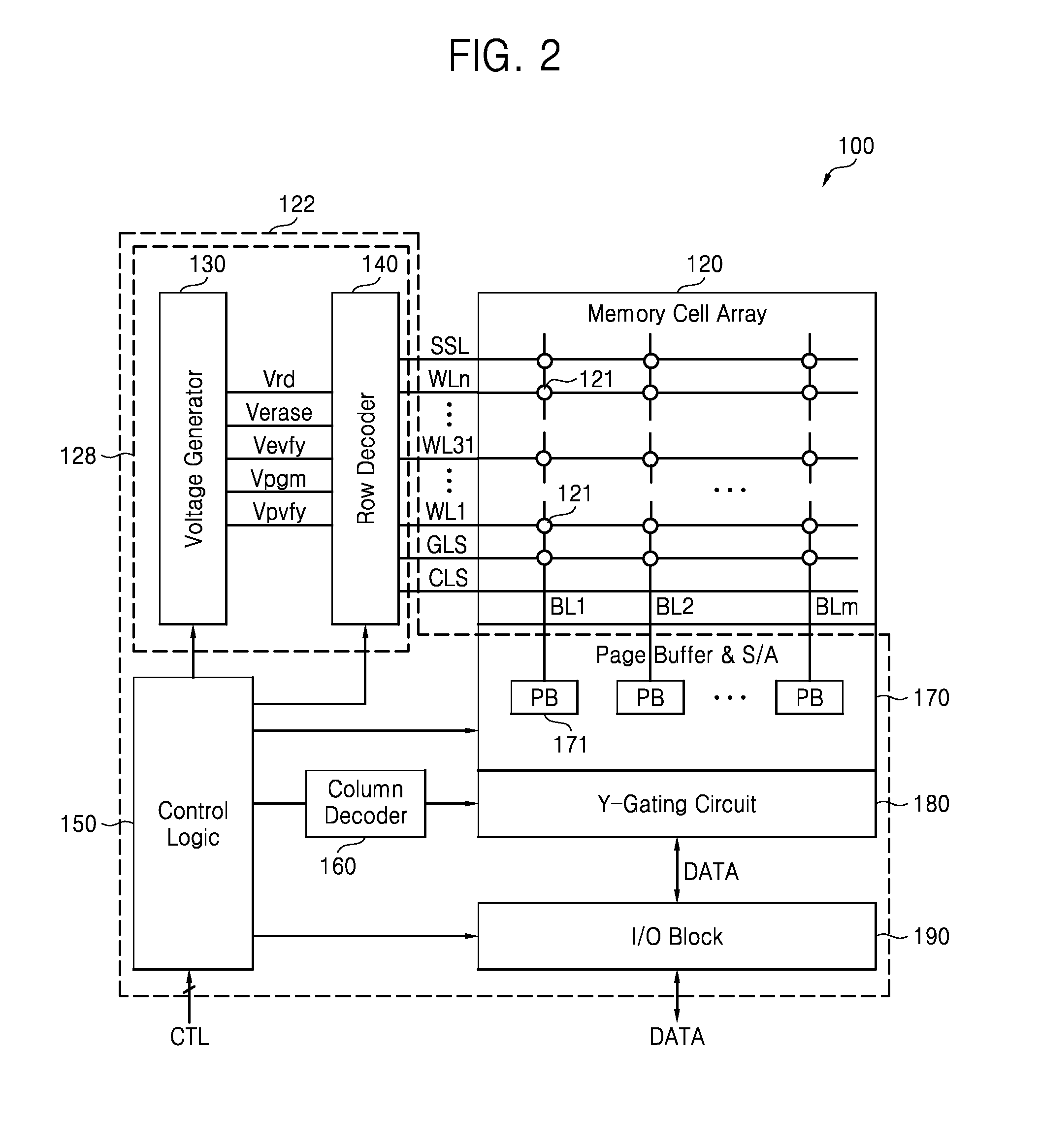
[0025]The inventive concept now will be described in some additional detail with reference to the accompanying drawings. The inventive concept may, however, be embodied in many different forms and should not be construed as being limited to only the illustrated embodiments. Rather, these embodiments are provided so that this disclosure will be thorough and complete, and will fully convey the scope of the invention to those skilled in the art. Throughout the written description and drawings, like reference numbers and labels are used to denote like or similar elements.

[0026]It will be understood that when an element is referred to as being “connected” or “coupled” to another element, it can be directly connected or coupled to the other element or intervening elements may be present. In contrast, when an element is referred to as being “directly connected” or “directly coupled” to another element, there are no intervening elements present. As used herein, the term “and / or” includes an...


PUM


Abstract

A method of programming a non-volatile memory device includes; defining a set of verification voltages, setting a maximum verification voltage among verification voltages that are less than or equal to a first target programming voltage to be a target verification voltage, calculating a number of extra pulses based on the target verification voltage and the first target programming voltage, verifying whether a threshold voltage of the memory cell is equal to or greater than the target verification voltage by applying an incremental step pulse program (ISPP) pulse to the memory cell and then applying at least one verification voltage in the set of verification voltages to the memory cell, and further applying the ISPP pulse to the memory cell a number of times equal to the number of extra pulses when the threshold voltage is verified to be equal to or greater than the target verification voltage.

Description

CROSS-REFERENCE TO RELATED APPLICATIONS[0001]This application claims the benefit of Korean Patent Application No. 10-2013-0028265 filed on Mar. 15, 2013, the subject matter of which is hereby incorporated by reference.BACKGROUND[0002]The inventive concept relates to non-volatile memory devices, and more particularly, to non-volatile memory devices having reduced programming periods while maintaining acceptable bit error rates (BER). The inventive concept also relates to methods of programming such non-volatile memory devices.[0003]In certain conventional nonvolatile memory devices, such as flash memory, data is stored by defining the threshold voltage of a constituent memory cell. The definition (or adjusting) of a memory cell threshold voltage such that it falls within one of a number of defined threshold voltage distributions may be accomplished using a variety of programming methods. For example, in one class of programming methods, a sequence of high-voltage pulses having variab...

Claims


Application Information

Patent Timeline
IPC IPC(8): G11C16/10
CPCG11C16/10G11C11/5628G11C16/3459G11C16/34
Inventor SHERESHEVSKI, YOAVDOR, AVNERDASHEVSKY, SHMUELKONG, JUN JINYOON, PIL SANG
Owner SAMSUNG ELECTRONICS CO LTD
Learn More