Polar Receiver Architecture and Signal Processing Methods
a receiver and signal processing technology, applied in the direction of digital transmission, simultaneous amplitude and angle demodulation, transmission, etc., can solve the problems of poor performance and high bit error rate (ber)
- Summary
- Abstract
- Description
- Claims
- Application Information
AI Technical Summary
Benefits of technology
Problems solved by technology
Method used
Image
Examples
Embodiment Construction
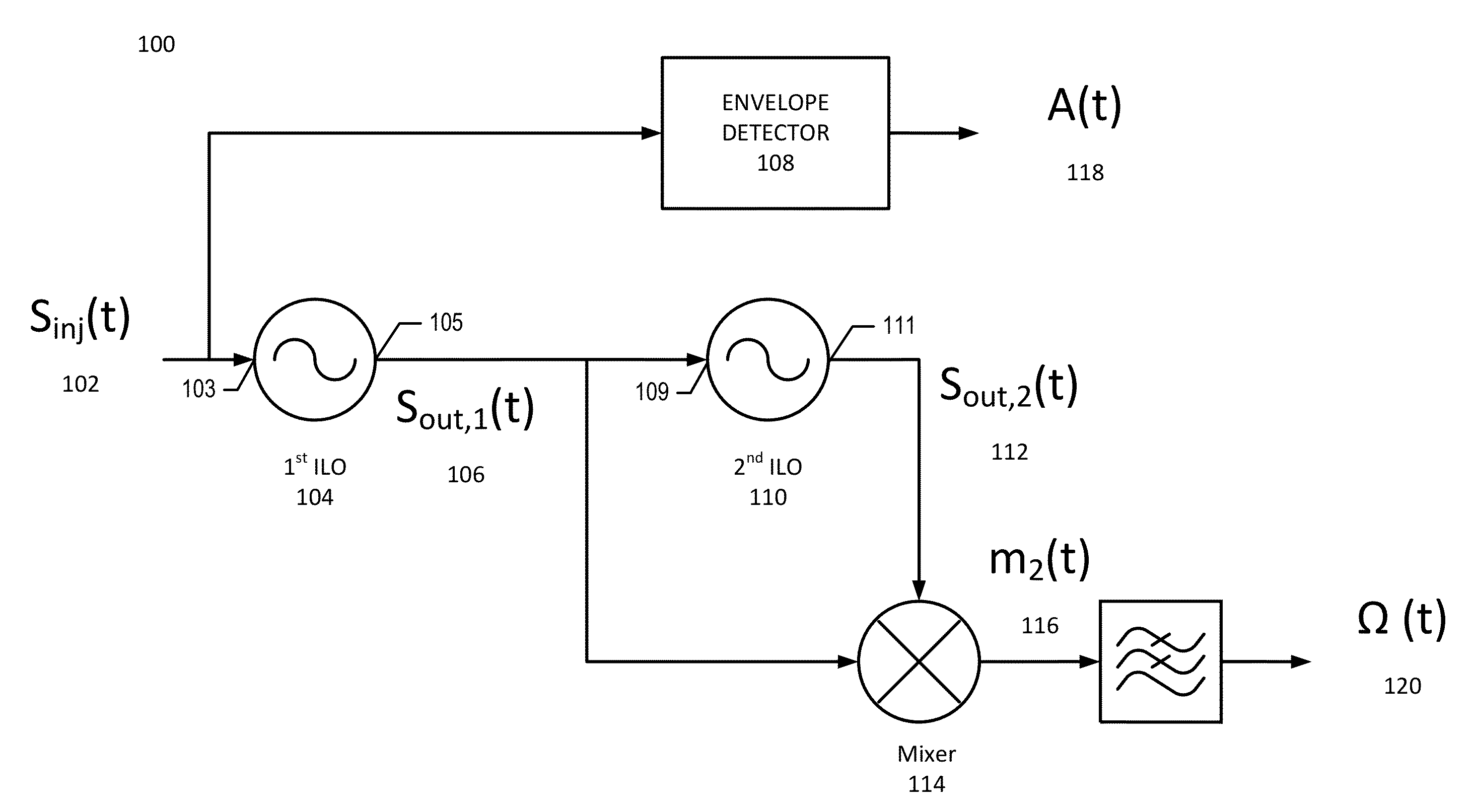
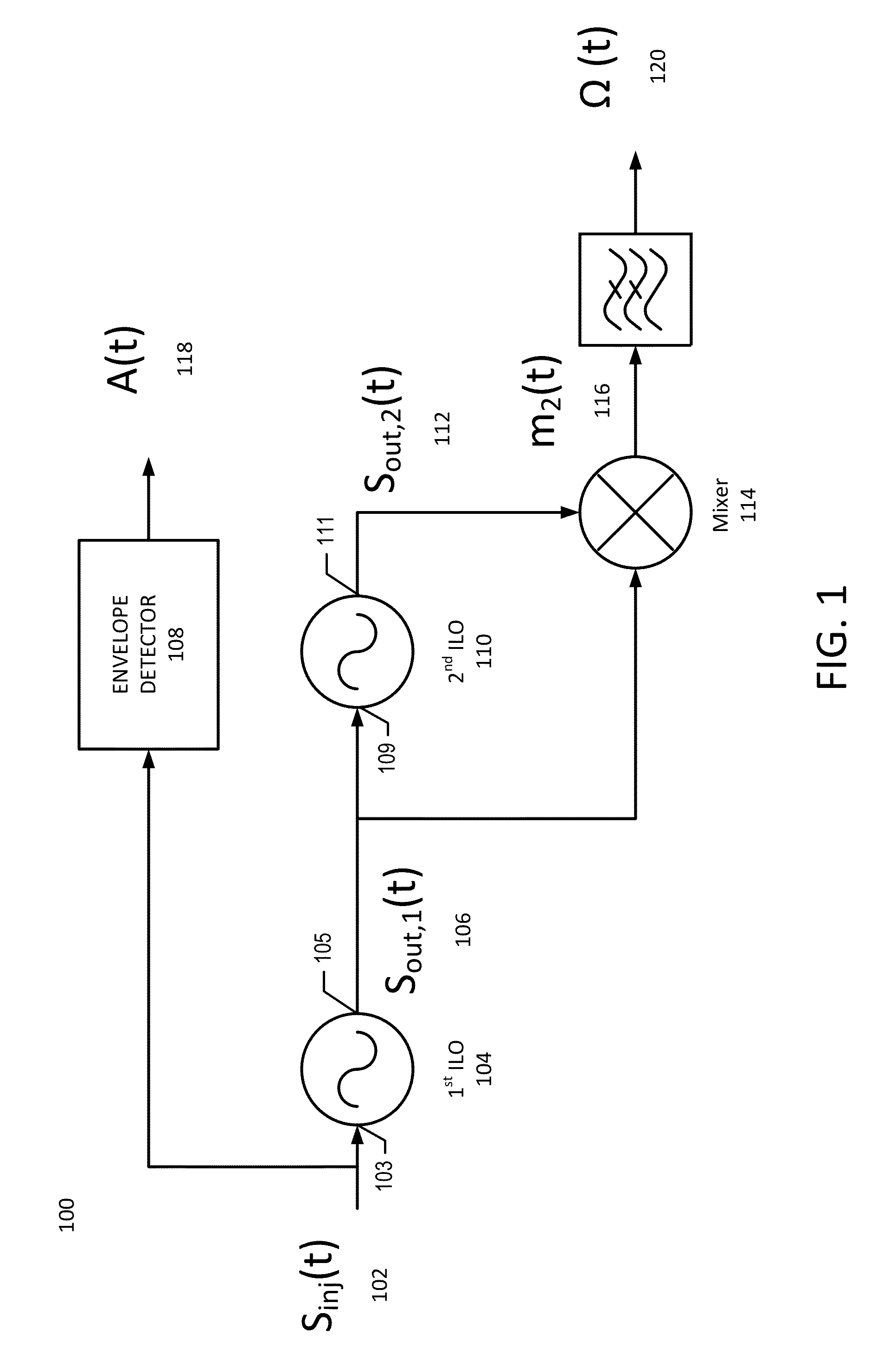
[0015]With reference to FIG. 1, a block diagram of a polar receiver 100 will be described in accordance with some embodiments. The injection signal Sinj(t) 102, which is a received modulated signal having a variable phase component, is applied to an input node 103 of the second harmonic injection locked oscillator (ILO) 104 (also referred to herein as a harmonic ILO). The output signal of the harmonic ILO Sout,1(t) 106 at node 105 has a compressed variable phase component, as will be described below. The compressed variable phase signal 106 is applied to input node 109 of the fundamental injection locked oscillator ILO 110 (also referred to herein as a fundamental ILO), and undergoes a delay to generate the output signal Sout,2(t) 112 at output node 111. That is, Sout,1(t) 106 and Sout,2(t) 112 are related by a time delay imposed by fundamental ILO 110. Sout,1(t) 106, which is the phase compressed signal, and Sout,2(t) which is the delayed phase compressed signal, are applied to mix...
PUM
 Abstract
Description
Claims
Application Information
 - R&D
- Intellectual Property
- Life Sciences
- Materials
- Tech Scout
- Unparalleled Data Quality
- Higher Quality Content
- 60% Fewer Hallucinations
Browse by: Latest US Patents, China's latest patents, Technical Efficacy Thesaurus, Application Domain, Technology Topic, Popular Technical Reports.
© 2025 PatSnap. All rights reserved.Legal|Privacy policy|Modern Slavery Act Transparency Statement|Sitemap|About US| Contact US: help@patsnap.com


