Measurement of wave-front aberration in a small telescope remote imaging system using scene-based wave-front sensing

a remote imaging and wave-front aberration technology, applied in the field of adaptation optics, can solve problems such as internal wavefront sensor error that must be measured, path distortion, airy image distorted,

Inactive Publication Date: 2014-09-18
LAWRENCE LIVERMORE NAT SECURITY LLC
View PDF2 Cites 12 Cited by
  • Summary
  • Abstract
  • Description
  • Claims
  • Application Information

AI Technical Summary

Benefits of technology

[0025]It is an object of the invention to provide reference-free compensated imaging methods and apparatuses to perform the methods. In a broad sense, the method makes an estimation of the Fourier phase of a series of images of a target. The Fourier magnitude of the series of images is obtained by dividing the power spectral density of the series of images by an estimate of the power spectral density of atmospheric turbulence from as series of scene based wave front sensor (SBWFS) measurements of the target. A high-resolution image of the target is recovered from the Fourier phase and the Fourier magnitude. Other objects will be apparent to those skilled in the art as a result of the teachings herein.
[0026]An embodiment of the method includes acquiring a se

Problems solved by technology

However, owing to optical propagation phase distortions, φ, encountered by the reference beam on its path toward the receiver 110, the wavefronts of this beam will be aberrated, resulting in a distorted image of an Airy disc pattern at camera 190.
As is known in the art, the path distortions in this scenario can stem from atmospheric turbulence, pointing and tracking errors, imperfect optical elements, thermal and mechanical perturbations, among other effects.
In actual implementations, there will be internal wavefront sensor error that m

Method used


Image

  • Measurement of wave-front aberration in a small telescope remote imaging system using scene-based wave-front sensing
  • Measurement of wave-front aberration in a small telescope remote imaging system using scene-based wave-front sensing
  • Measurement of wave-front aberration in a small telescope remote imaging system using scene-based wave-front sensing

Examples


Embodiment Construction

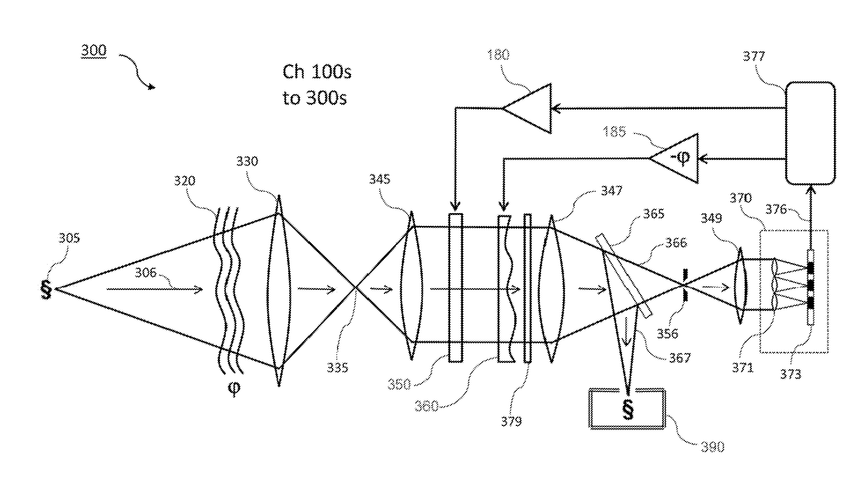
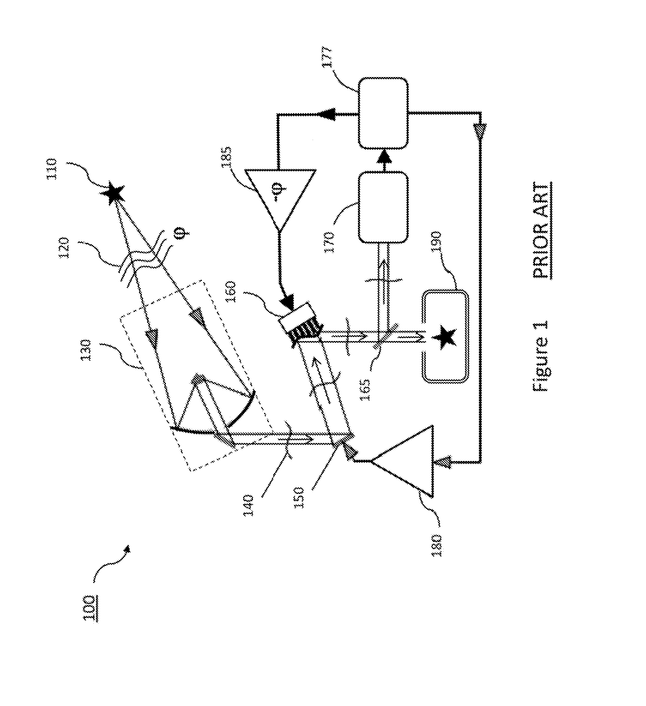
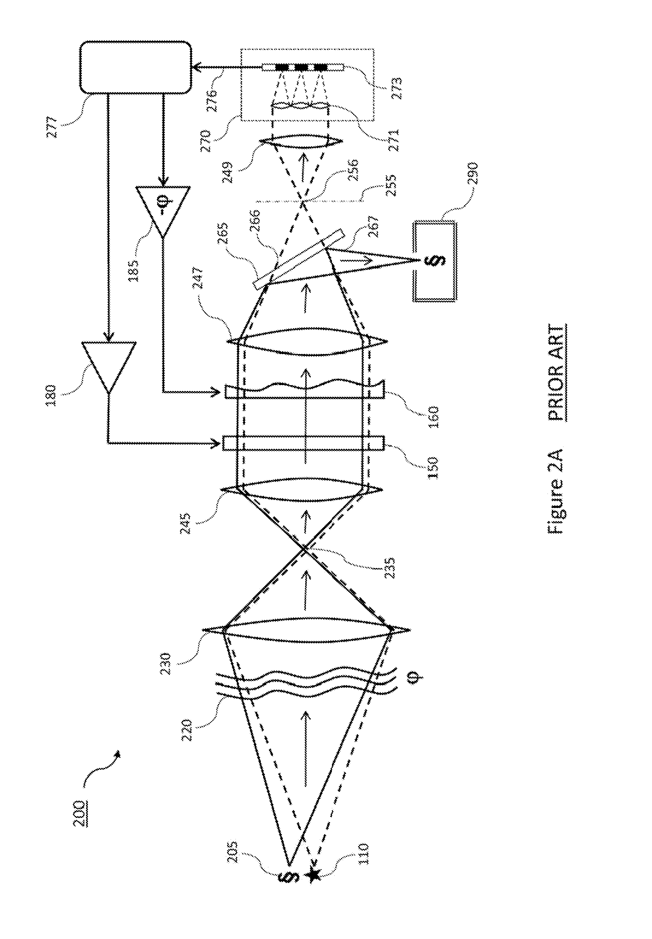
[0044]An exemplary embodiment of a reference-free compensated imaging system is shown in FIG. 3A. The goal of system 300 is similar to that of the prior art in FIG. 2A, namely, to enable high-quality imaging of an extended object 305, whose image-bearing beam may have experienced propagation-path distortions along an atmospheric path 320. In this embodiment, there is only a single beam that traverses the path distortions and is received by the image compensation system 300 - - - the image-bearing beam itself, 306. That is, as opposed to the prior art, there is no independent reference beam required to sample the path distortions. In the present case, the image-bearing beam 306 essentially emulates both the image-bearing beam 205 of the prior art, as well as the reference beam 110 of the prior art (both depicted in FIG. 2A).

[0045]As depicted in FIG. 3A, the propagation-path distorted, image-bearing beam 306 is incident upon telescope 330, and subsequently, traverses intermediate foca...


PUM


Abstract

Reference-free compensated imaging makes an estimation of the Fourier phase of a series of images of a target. The Fourier magnitude of the series of images is obtained by dividing the power spectral density of the series of images by an estimate of the power spectral density of atmospheric turbulence from a series of scene based wave front sensor (SBWFS) measurements of the target. A high-resolution image of the target is recovered from the Fourier phase and the Fourier magnitude.

Description

STATEMENT REGARDING FEDERALLY SPONSORED RESEARCH OR DEVELOPMENT[0001]The United States Government has rights in this invention pursuant to Contract No. DE-AC52-07NA27344 between the US. Department of Energy and Lawrence Livermore National Security, LLC, for the operation of Lawrence Livermore National Laboratory.BACKGROUND OF THE INVENTION[0002]1. Field of the Invention[0003]The present invention relates to adaptive optics, and more specifically, it relates to a reference-free compensated imaging system for recovering a high resolution image of a target.[0004]2. Description of Related Art[0005]The basic elements of a typical (prior art) adaptive optics system 100 are shown in FIG. 1. The goal of such systems is to provide real-time compensation for propagation errors, as encountered by optical beams, as they travel through dynamic distorting paths, including turbulent atmospheres, optical pointing errors, imperfect optical elements, multi-mode optical fibers, etc.[0006]By compensati...

Claims


Application Information

Patent Timeline
IPC IPC(8): G06T5/00
CPCG06T5/003G06T5/10G06T3/4053
Inventor POYNEER, LISA A.BAUMAN, BRIAN J.
Owner LAWRENCE LIVERMORE NAT SECURITY LLC
Why Eureka
Try Eureka