Medical system

a medical system and system technology, applied in the field of medical systems, can solve the problems of increasing workload on the doctor or the radiologist, doctor's inability to directly operate the operation portions of medical equipment, and doctor's frustration, so as to prevent in-hospital infection, facilitate carrying close to the patient, and keep the surface clean

Active Publication Date: 2014-09-18
FUJIFILM CORP
View PDF15 Cites 51 Cited by
  • Summary
  • Abstract
  • Description
  • Claims
  • Application Information

AI Technical Summary

Benefits of technology

[0022]The mobile apparatus is preferably a tablet computer, a handheld computer, or a personal digital assistant. This type of the mobile apparatus can be easily carried close to the patient.
[0023]In particular, the tablet computer does not have a keyboard, a mouse, and the like, and does not have a concave-convex surface. Therefore, for example, the tablet computer surface may be subjected to a sterilization treatment after the surgical operation, to keep the surface clean and to prevent in-hospital infection.

Problems solved by technology

Therefore, the doctor cannot directly operate the operation portions of the medical apparatuses.
However, in a case where the technician cannot operate the medical apparatus as requested by the doctor rapidly and appropriately, the doctor feels very frustrated.
Thus, the workload on the doctor or the radiologist is increased, and the procedures including the change of the image capturing conditions and the positioning of the subject cannot be rapidly performed.

Method used


Image

  • Medical system
  • Medical system
  • Medical system

Examples


first modification

[First Modification]

[0304]In the first modification of this embodiment, in a case where the doctor 18 clicks a desired area on the screen of the display portion 192 with a finger as shown in FIG. 15A, the next capturing of the image of the patient 16 is performed such that the clicked area is displayed in the center of the screen. Thus, in the image acquired by the next capturing, the clicked area is displayed in the center of the screen of the display portion 192 as shown in FIG. 15B. In the following description, the moving image acquired in the fluoroscopic image capturing is displayed on the screen of the display portion 192 in the same manner as FIG. 6A by way of example.

[0305]As shown in FIG. 15A, in a case where the moving fluorography image is displayed on the screen of the display portion 192 and the circled area containing the narrowed portion 224 is an area of concern 296 of the doctor 18, the doctor 18 clicks the area of concern 296 with a finger. The control portion 132...

second modification

[Second Modification]

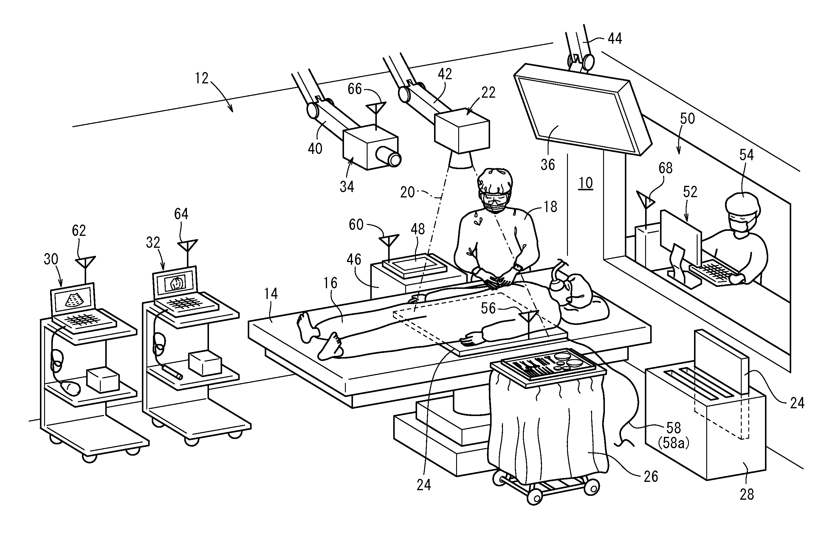
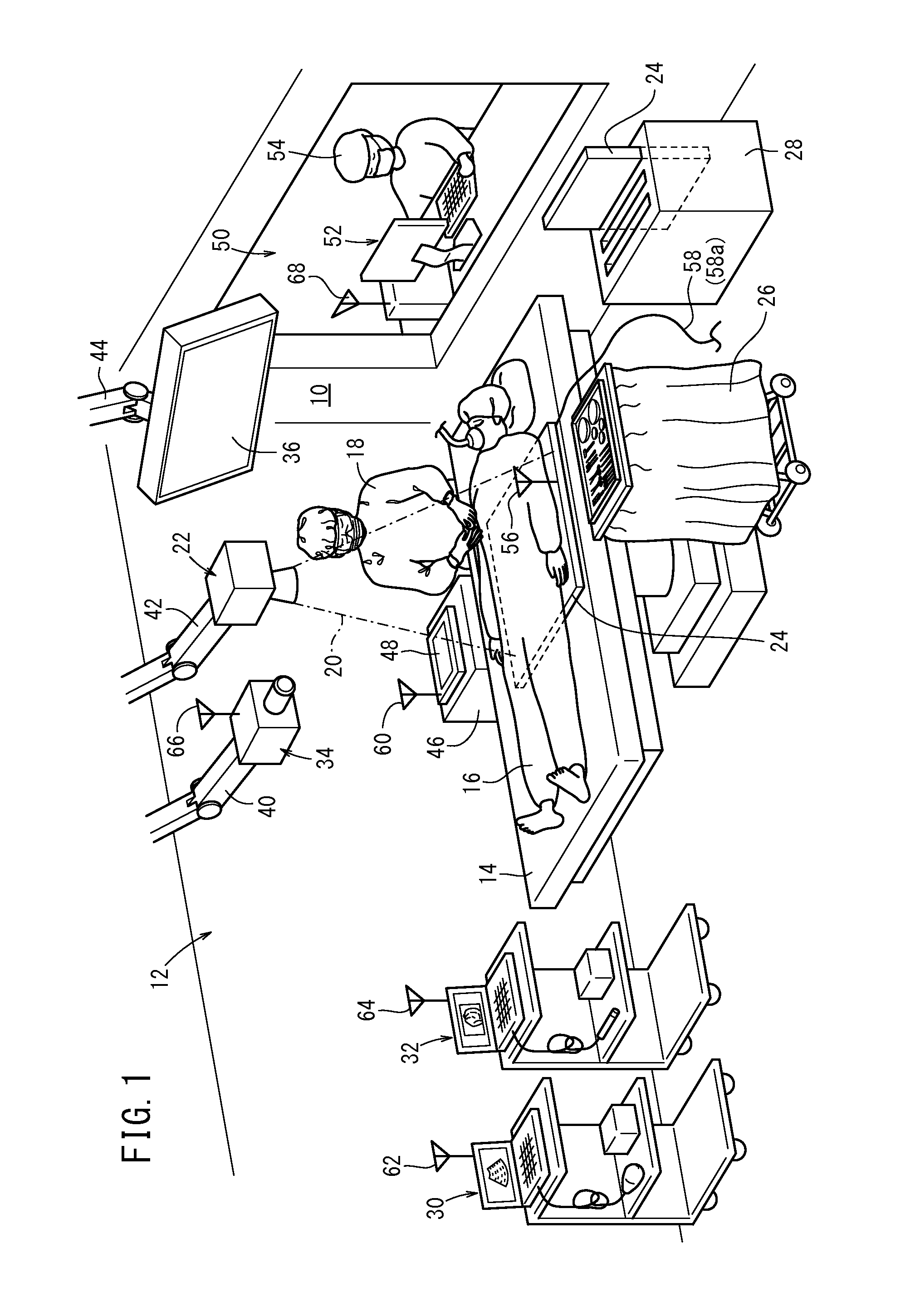
[0316]In the above description, the doctor 18 operates on the patient 16 in the operating room 12.

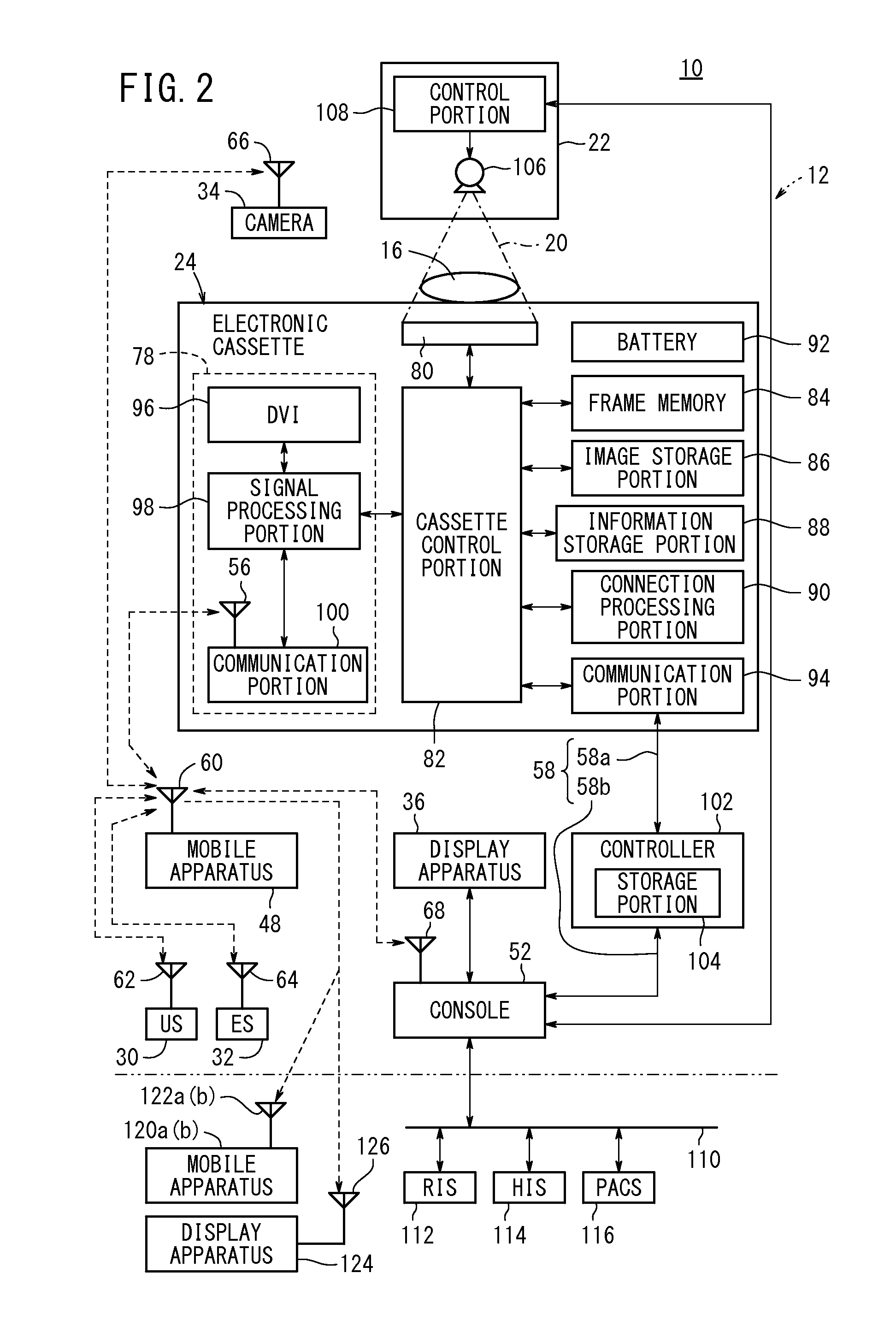
[0317]In the second modification of this embodiment, as shown in FIG. 16, in a case where the patient 16 lies down on a bed 300 in a patient room 298 or the like in the medical institution, the technician 54 or the doctor 18 carries a round cart 302 to the patient room 298 and performs therein a diagnosis of the patient 16 (such as the radiographic image capturing using the radiation source 106 and the radiographic image capturing apparatus 24).

[0318]In the round cart 302, a base unit 306 is disposed as a housing on a dolly 304. The console 52, which has a display operation portion 308 with the display portion 192, the operation portion 194, and the exposure switch 196 being integrated thereinto, is disposed in the base unit 306. Insertion slots, into which the radiographic image capturing apparatus 24 can be inserted, are formed on the base unit 306. The cradle 28 ...

third modification

[Third Modification]

[0351]In the third modification of this embodiment, the second modification (see FIG. 16) is partially modified as shown in FIG. 17.

[0352]In this modification, the patient 16 lies down on a bed 318 in the patient room 298. A straight rail 322 extends straight on the ceiling 320 of the patient room 298, and a base member 324 can be moved along the rail 322. The base member 324 is connected with a multijoint arm 326, and the radiation output apparatus 22 is attached to the end of the multijoint arm 326. The camera 34 is attached to the outer periphery of the radiation output apparatus 22. The base member 324 has an antenna 328. The base member 324 receives a control signal from the mobile apparatus 48 via a wireless communication link, and a drive mechanism (not shown) disposed in the base member 324 is actuated in response to the received control signal. Then, the base member 324 is moved along the rail 322 and acts to control the multijoint arm 326.

[0353]Thus, th...


PUM


Abstract

In a portable apparatus of a medical system, in a case where an operation unit receives an operation from a physician on the basis of the display contents of a display unit, the medical apparatus controlled as a result of the operation of the operation unit by an operator is defined by an operation control unit, and a signal in response to the operation contents received by the operation unit is transmitted from a transmission unit to the defined medical apparatus.

Description

CROSS-REFERENCE TO RELATED APPLICATIONS AND PRIORITY CLAIM[0001]This application is a Continuation of International Application No. PCT / JP2012 / 080885 filed on Nov. 29, 2012, which was published under PCT Article 21(2) in Japanese, which is based upon and claims the benefit of priority from Japanese Patent Application No. 2011-262836 filed on Nov. 30, 2011, the contents all of which are incorporated herein by reference.TECHNICAL FIELD[0002]The present invention relates to a medical system containing a plurality of medical apparatuses for performing a predetermined diagnosis or procedure on a test subject.BACKGROUND ART[0003]Medical systems, which contain a plurality of medical apparatuses for performing a predetermined diagnosis or procedure on a test subject, have been disclosed in Japanese Laid-Open Patent Publication Nos. 2007-175231, 2005-087612, 2004-344390, 2006-255395, and 2002-369787, etc.SUMMARY OF INVENTION[0004]For example, in a case where the medical system disclosed in t...

Claims


Application Information

Patent Timeline
Patent Type & Authority Applications(United States)
IPC IPC(8): A61B19/00A61B8/00A61B1/00A61B6/00
CPCA61B19/56A61B6/465A61B6/548A61B6/56A61B8/465A61B1/00011A61B8/56A61B1/0005A61B8/463A61B6/54A61B1/00006A61B8/54A61B2017/00212A61B2017/00221A61B1/00039A61B6/4233A61B6/4283A61B6/4405A61B8/0891A61B8/12A61B1/00016A61B1/00045A61B8/565A61B8/462A61B8/467A61B8/464A61B34/25A61B90/00
Inventor OHTA, YASUNORINISHINO, NAOYUKINAKATSUGAWA, HARUYASUIWAKIRI, NAOTOKITANO, KOUICHI
Owner FUJIFILM CORP
Why Eureka
Try Eureka